
Production introduction:
System failures happen. Replacing equipment is expensive. Often the cause of problems stays undetermined. Lightning damage is often subtle and the underlying cause of undocumented failure. The Lightning Strike Counter keeps track of the number of times that a facility or equipment has suffered a direct strike and can assist in determining the need for additional means of security such as grounding, surge suppression, and lightning protection.
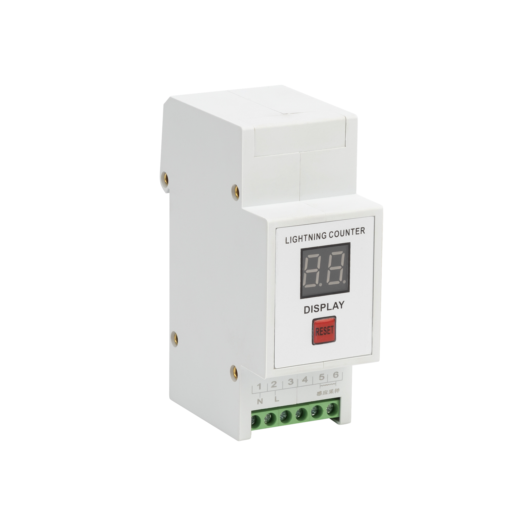
The lightning counter is suitable for counting the number of lightning discharge currents of various lightning protection devices. The counting times are two digits, which expands the function that only counted in units in the past, up to 99 times. The lightning counter is installed on the lightning protection module that needs to discharge lightning current, such as the ground wire of the lightning protection device. The initial counting current is 1 Ka, and the maximum counting current is 150 kA. Power failure in the lightning counter can protect data for up to 1 month. The lightning counter is equipped with a current transformer.
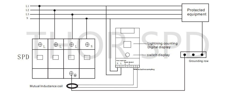
When installing and using, put the core of the current transformer into the PE wire of the surge protector, and lead the two very wires of the times coil of the transformer into the terminals 5 and 6 of the lightning counter and connect them firmly. When a surge occurs, the surge protector discharges the lightning current into the ground, and the transformer induces the lightning current. After sampling, it is coupled to the counter. After the counter processes the lightning signal through the internal integrated circuit, it is displayed on the LED digital tube. Switch to display the number of lightning discharge currents.
The lightning current counter has six binding posts. The two binding posts 1, 2 are connected to the N and L wires to provide charging power for the counter; the middle 3 and 4 two binding posts, short-circuit the counter to reset the counter; 5, 6 two Two terminals lead into the two wires of the current transformer coil.

|
Electrical Characteristics |
|||
|
Type |
Working voltage |
Action current |
Sampling model |
|
TRSC |
220VAC |
1KA-150KA(8/20μs) |
Mutual inductance sampling |
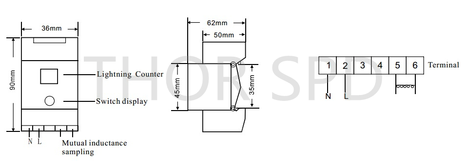
Dimension:

Wiring Diagram:
