Introduction
Surge protection is a critical safety measure, along with lightning rod, designed to protect electrical circuits and equipment from damaging overvoltages caused by direct lightning strikes, indirect lightning effects like potential coupling, short circuits, and abnormal power switching. Effective surge protection minimizes the risk of costly damage and sustains your electrical systems.
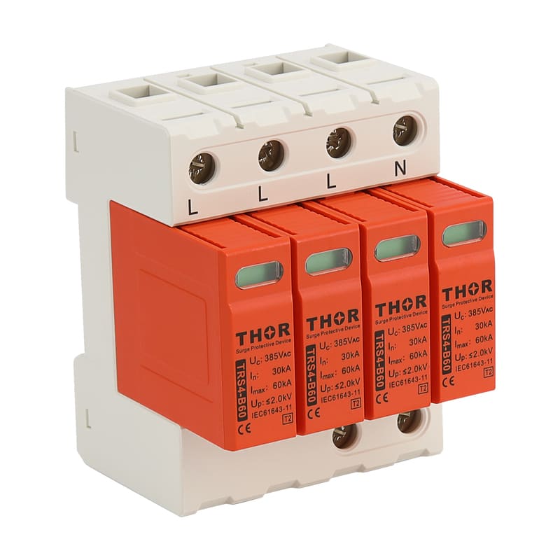
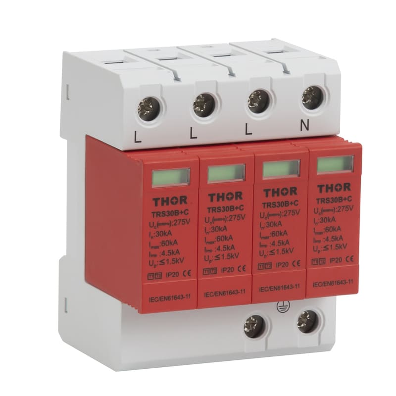
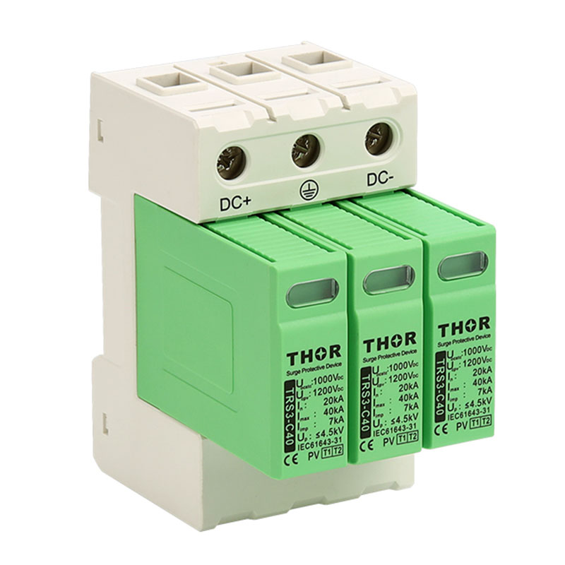
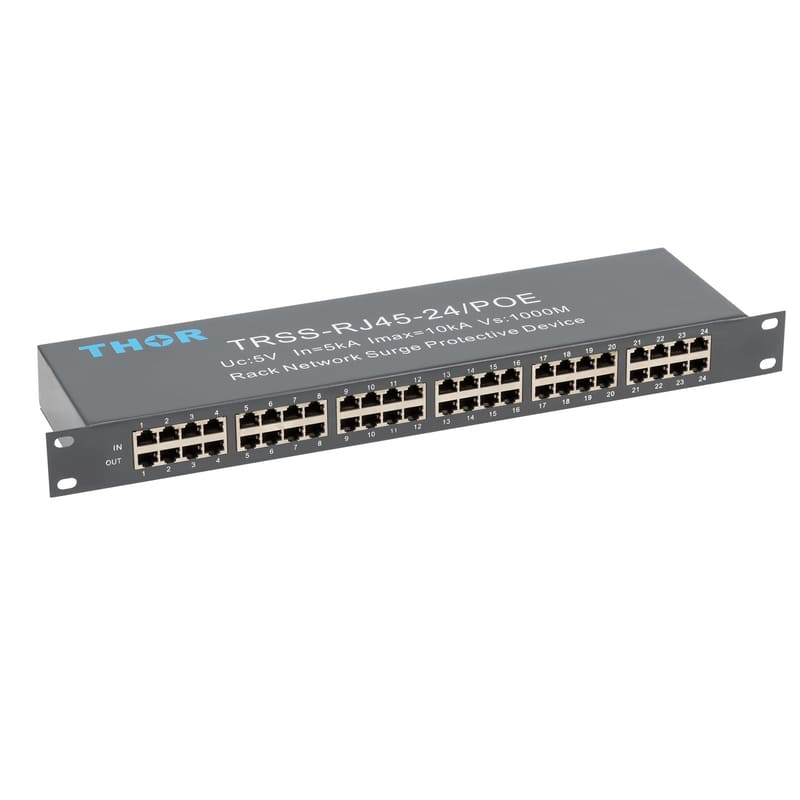
Surge Protective Devices (SPDs) are essential components crafted to divert damaging electrical surges safely to ground or neutral, thereby protecting connected equipment from overvoltage events. According to the IEC 61643-11 standard, SPDs are typically classified into Type 1 (CLass B), Type 2 (CLass C), and Type 3 (CLass D). In addition to standard classifications, there are also specialized point-of-use SPDs tailored for Ethernet lines, signal systems, lighting circuits, and other sensitive electronic applications.
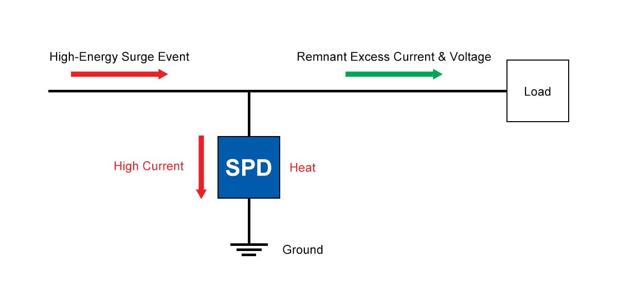
Figure 1 - Surge protective device working principle
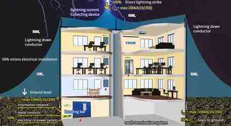
While each type of Surge Protective Device (SPD) serves a specific role within a protection system, modern electrical installations increasingly emphasize the importance of a cascaded surge protection strategy. By deploying multiple SPDs at different levels of the power distribution network, the overall resilience and effectiveness of surge protection are significantly enhanced.
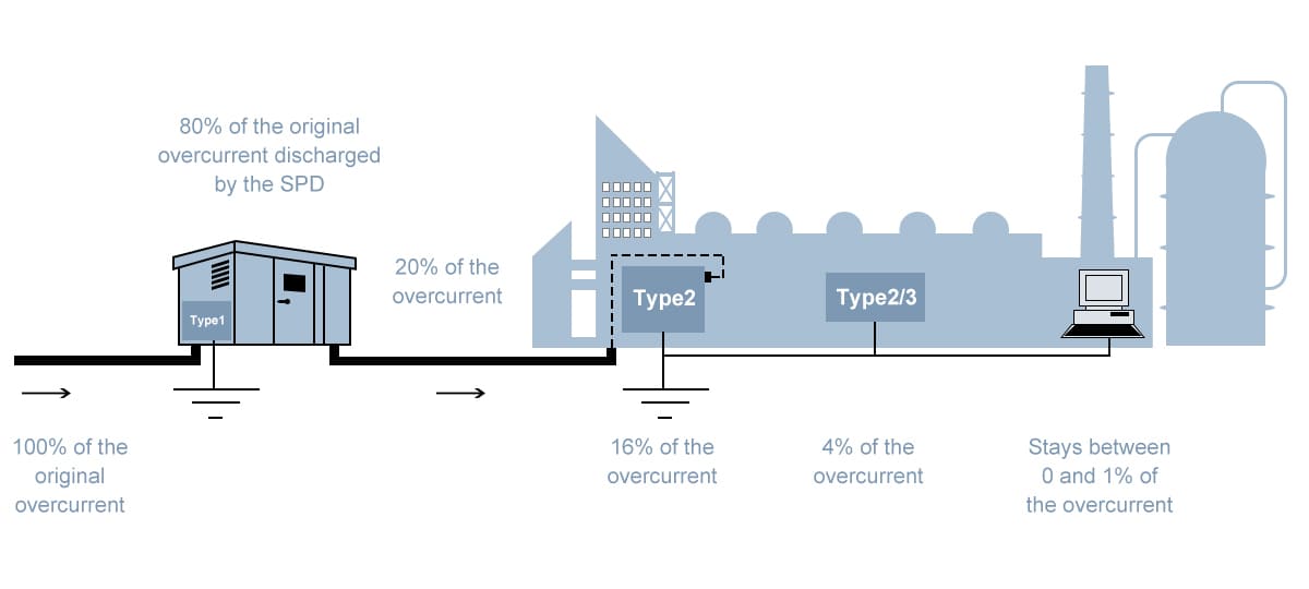
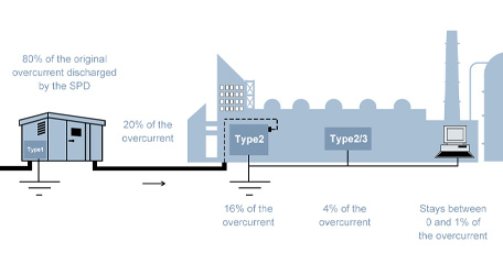
Figure 2 - Attenuated surge energy in cascaded surge protection
Without cascading, A single SPD may offer sufficient protection for a specific part of the circuit, but it must absorb the entire surge energy, which can shorten its lifespan or lead to failure during large surge events. With a layered system, energy is gradually reduced at each stage, improving system longevity, reliability, and compliance with standards like IEC 61643-11 and surge protection coordination rules.
What is layered/cascaded surge protection
Layered or cascaded surge protection is a strategic approach in electrical system design where multiple surge protective devices are installed at different levels of power distribution network to offer comprehensive and meshed protection.
Each type of SPD is engineered to handle specific levels and types of overvoltage energy. Table 1 below outlines the characteristics of each SPD type, including the corresponding test waveform and recommended installation location.
|
SPD Type |
Test waveform |
Protection level |
Installation location |
|
Type 1 |
10/350 µs |
High-energy surge (direct lightning) |
Main service entrance/building entry point |
|
Type 2 |
8/20 µs |
Medium-energy surge (indirect lightning, switching) |
Sub-distribution boards/main panels |
|
Type 3 |
Combination wave (1.2/50 µs voltage, 8/20 µs current) |
Low-energy surge (residual) |
Closeto sensitive equipment/socket outlets |
Table 1 - SPD types, waveforms and applications
By deploying Type 1, Type 2, and Type 3 SPDs in a coordinated manner—from the main service entrance to sub-distribution panels, and finally to sensitive equipment—surge energy is gradually reduced at each stage. The layered defense helps:
● Prolong the lifespan of SPDs
● Enhance overall system reliability
● provide more complete protection against both direct lightning strikes and internal switching surges
Layered surge protection is not only a best practice but also aligns with IEC 61643-11 coordination standards and EMC (Electromagnetic Compatibility) requirements in modern installations.
By coordinating SPDs, progressive and integrated protection against overvoltages is provided, without any single SPD being responsible for absorbing the entire surge energy.
Is layered/cascaded surge protection necessary?
While layered or cascaded surge protection offers superior system resilience, layered protection is not universally mandatory.
Surge protection strategies vary widely depending on the scale and type of electrical system being protected. The implementation of cascaded surge protection largely depends on the characteristics and requirements of the protected circuit.
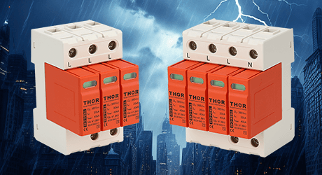
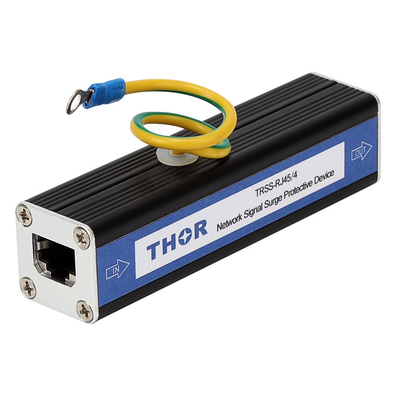
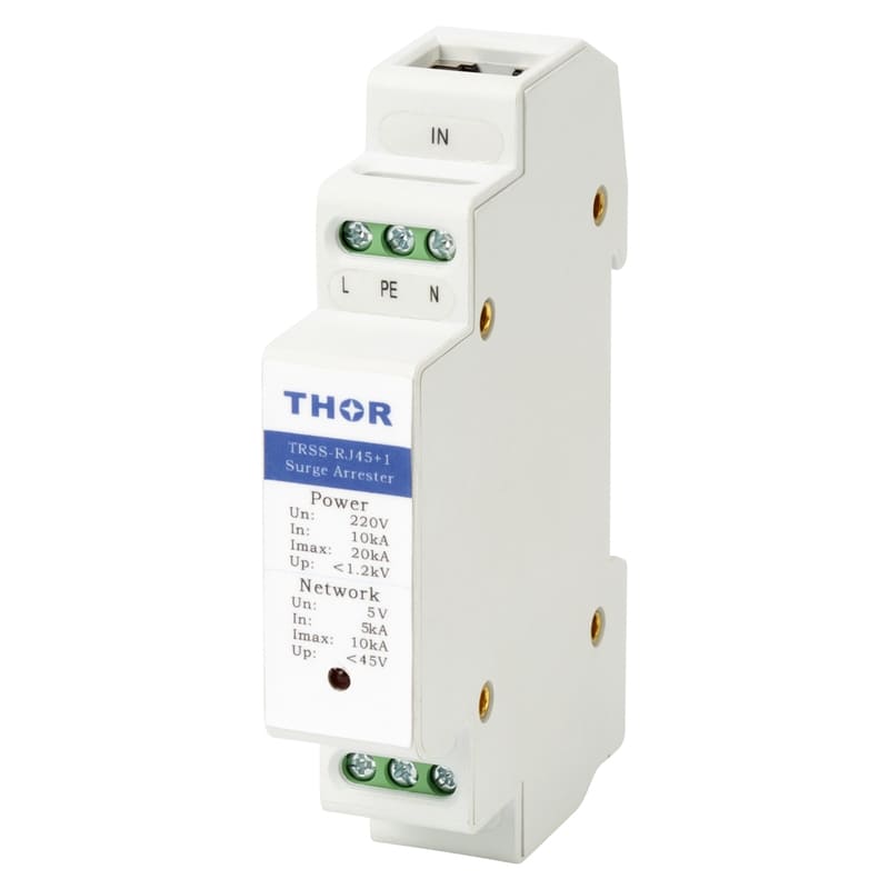
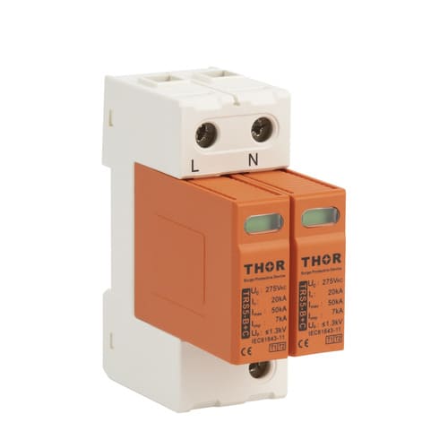
For instance, in low-exposure environments such as residential installations, surge protection is typically designed to address limited surge energy levels and fewer transient sources. In such cases, a compact surge protection setup combining a Type 1+2 TRS5 surge arrester at the main distribution board and a localized Type 3 TRSS SPD at sensitive terminal equipment is considered technically sufficient.
 |
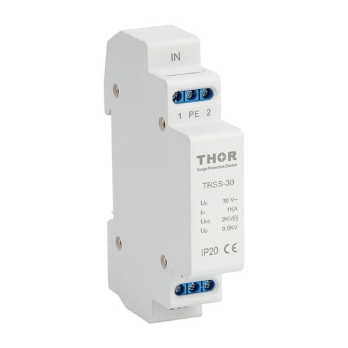 |
| TRS5 - Type 1+2 Surge arrester | TRSS - Type 3 surge protection device |
The Type 1+2 SPD at the service entrance handles high-energy lightning and switching surges, while the Type 3 SPD, installed near sensitive equipment, filters residual overvoltages and high-frequency noise that may bypass upstream protection.
The configuration, while streamlined, still adheres to coordination principles by distributing the surge energy dissipation task across two distinct protection stages. When correctly dimensioned and installed with proper impulse current rating (Iimp), voltage protection level (Up), and response time, the setup maintains effective energy gradation across protection stages.
For environments with minimal surge exposure - such as buildings with no external lightning protection system or those connected via underground cabling - this level of protection is often both technically and economically justified. However, the installation must still meet the required coordination distances and bonding principles to maintain effective voltage limitation and SPD longevity under repeated transient stress.
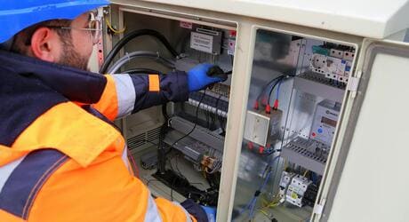
In contrast, Industrial and commercial power systems, characterized by extended distribution networks and diverse load types, exhibit increased susceptibility to both high-energy and low-level transient events. Surge entry points can originate from external sources such as direct lightning currents via service entrances, or from internal sources including load switching, motor start-ups, and capacitor bank operations. The presence of interconnected high-voltage equipment and sensitive control or data lines further elevates the system exposure to destructive overvoltages.
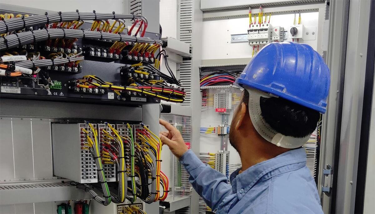
Figure 3 - Complex industrial electrical circuit wiring
To achieve effective protection, a multi-stage surge mitigation approach is required. Type 1 SPDs, installed at the service entrance, provide protection against direct lightning currents and high-magnitude surges. Type 2 SPDs, typically mounted at distribution panels, suppress residual energy not fully attenuated by upstream devices. Type 3 SPDs, located near end-use equipment, mitigate low-energy, high-frequency transients and contribute to local filtering of conducted disturbances.
Adoption of SPDs must align with internationally recognized technical frameworks to provide system performance and protection integrity.
Additionally, a properly coordinated SPD system contributes to the suppression of conducted electromagnetic disturbances. By attenuating transient-induced noise, surge protection enhances overall electromagnetic compatibility (EMC), stabilizes control signal behavior, and maintains system performance in environments where both power quality and data integrity are mission-critical.
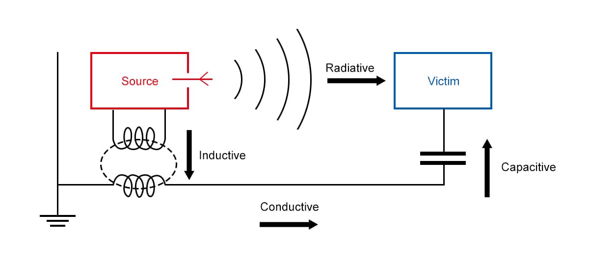
Figure 4 - How EMC issue arise in electrical systems
Best Practices to Install and Coordinate Cascading SPDs
IEC 61643-11 outlines testing protocols and classification for SPDs based on energy-handling capabilities. UL 1449 provides safety and compliance benchmarks, while IEEE C62.41 defines representative surge waveforms and guides system-level coordination practices.
I. Coordination Distance
Effective energy gradation between SPDs requires maintaining a minimum coordination distance between protection stages. When surge protective devices are installed too closely, their protection curves may overlap, leading to improper surge sharing and reduced efficiency.
A general rule recommends a minimum of 10 meters of cable length between two consecutive SPD stages. The regulated separation allows the first SPD to absorb the majority of the surge energy while the downstream SPD handles
residual voltage.
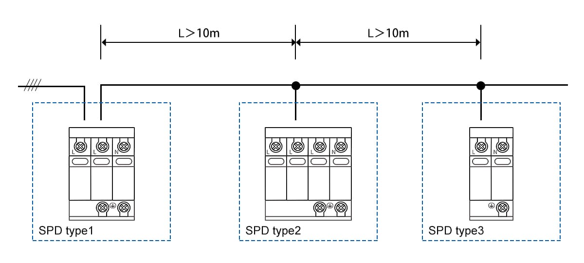
Figure 5 - Cabling length requirement among each stage of coordinated SPDs
In cases where physical space does not allow sufficient separation, impedance elements such as decoupling inductors or coordination coils should be inserted to artificially introduce the required impedance. Within the circuit, they function to support voltage drop formation between SPD stages, maintaining proper timing and response differentiation.
II. Earthing and Bonding
All SPDs function by diverting overvoltage energy to a low-impedance reference point - typically the ground. A high-integrity earthing system with low impedance is critical to facilitate the fast discharge of surge currents.
Equipotential bonding must be implemented at the main distribution board, linking incoming service lines, protective earth (PE), and the SPD terminals to a common reference. Failure to provide tight equipotential zones results in voltage potential differences during surge events, increasing the risk of flashover or insulation failure.
Make sure all exposed conductive parts are bonded to a common earth potential - this minimizes potential difference during a surge and ensures your SPD layers work as intended.
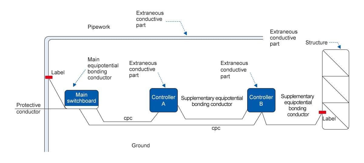
Figure 6 - Equipotential bonding in cascaded surge protection systems
III. Wiring and Connection Practices
SPDs must be connected using short, straight, and low-inductance conductors. Loop impedance and wiring length directly influence the residual voltage at the SPD terminals. Excessive wiring length adds inductive reactance, which may delay surge diversion and increase the voltage stress on protected equipment.
Conductors should be routed in parallel paths to minimize impedance and avoid sharp bends or coils, which contribute to increased inductance. For panel-mounted installations, connection to busbars is preferred over long terminal runs.
IV. Fuse and Circuit Breaker Coordination
Each SPD must be properly backed by a fuse or circuit breaker selected based on the SPD’s nominal discharge current (In), impulse current rating (Iimp), and short-circuit withstand capacity. Inadequate overcurrent protection can result in nuisance tripping or failure to disconnect during extreme fault conditions.
Manufacturer specifications typically include recommended fuse ratings to match SPD thermal disconnection behavior. Backup protection also prevents fire hazards in case of SPD degradation or short-circuiting under repeated surges.
Conclusion
Cascaded surge protection has become a key strategy in modern electrical infrastructure, offering enhanced resilience through the strategic deployment of multiple SPD types across different levels of a power distribution system. While full-scale layering may not be necessary in every installation - such as low-risk residential environments - it is strongly recommended for industrial and commercial applications where the protection to risk and impact of surge events can not be compromised.
Effective implementation requires strict adherence to coordination principles. Critical factors such as minimum separation distances between SPD stages, low-impedance equipotential bonding, optimized conductor routing, and correctly rated backup protection devices must be addressed during system design and installation. Compliance with international standard - such as IEC 61643-11, UL 1449, and related guideline - is essential to maintain protective integrity, device longevity, and system performance under harsh environment and intense surge impact.