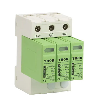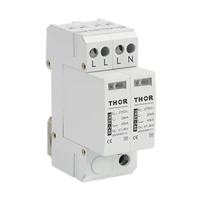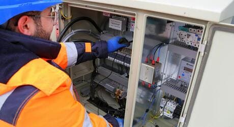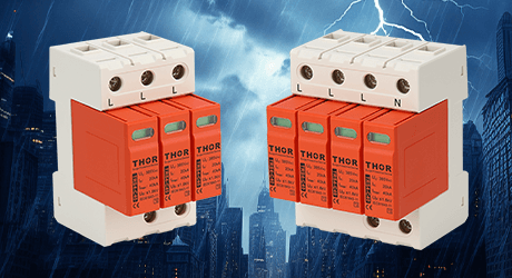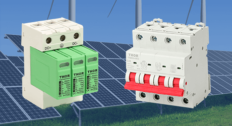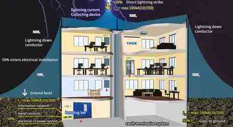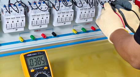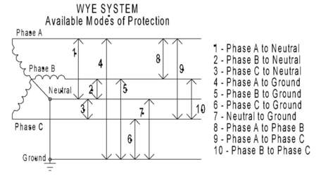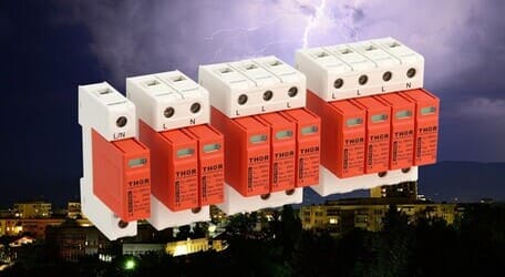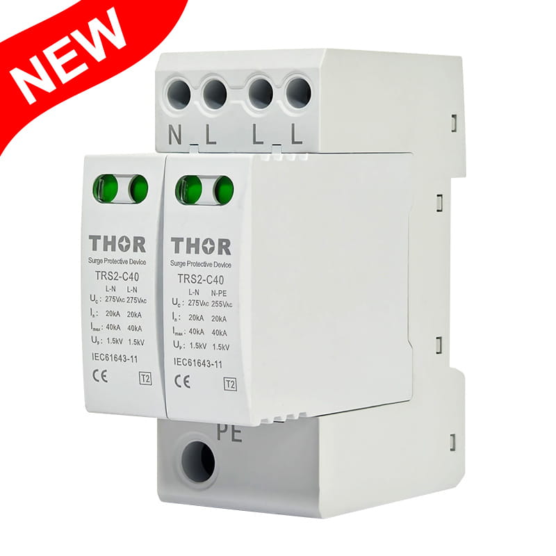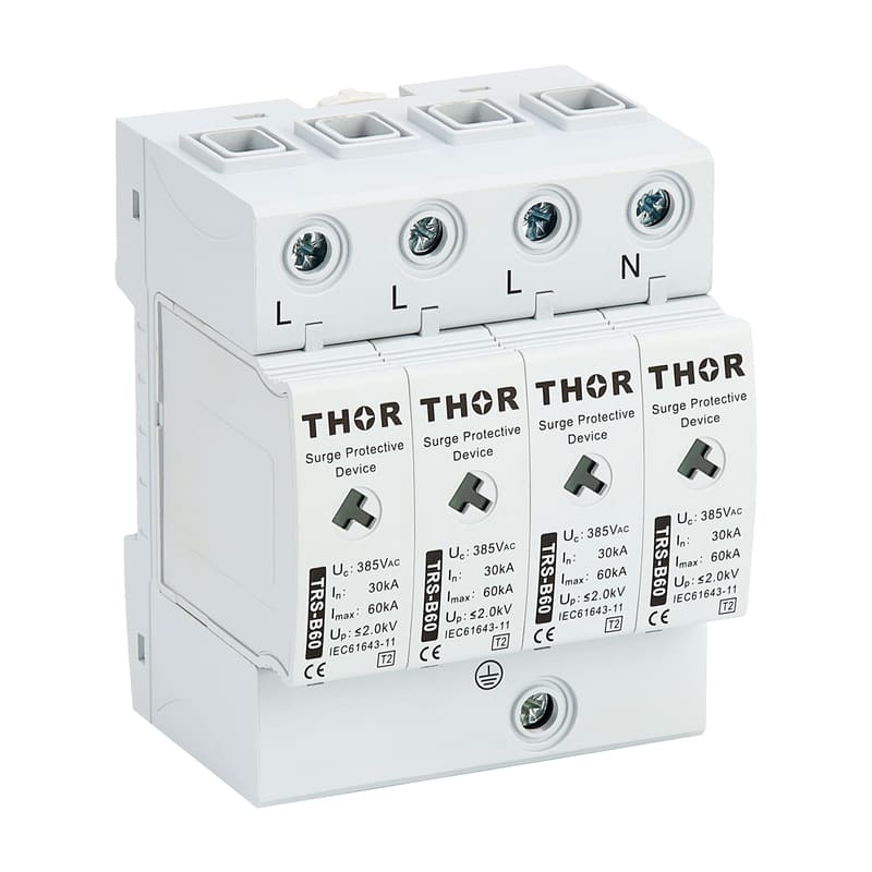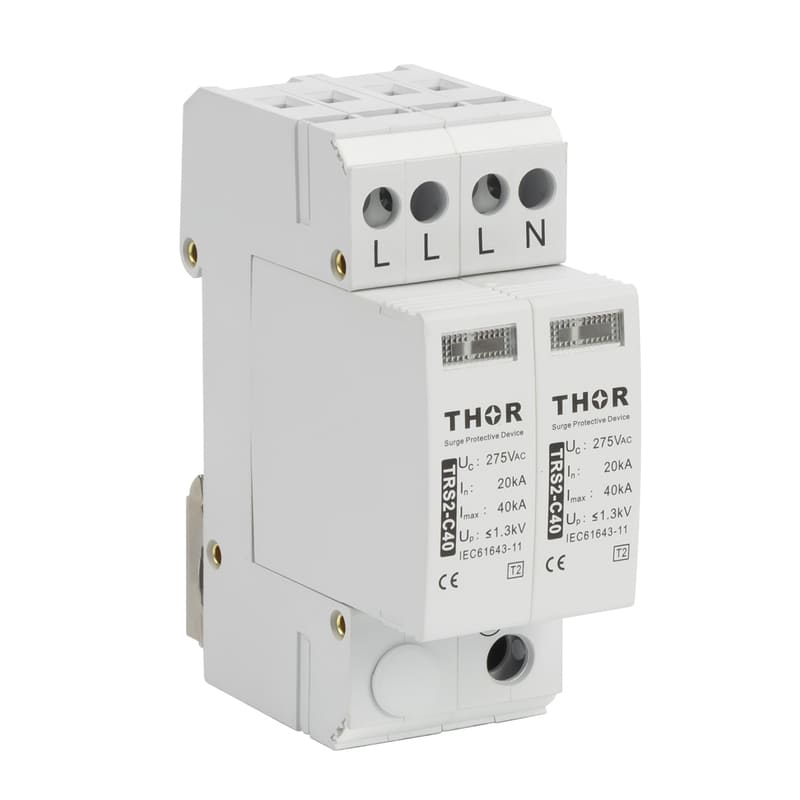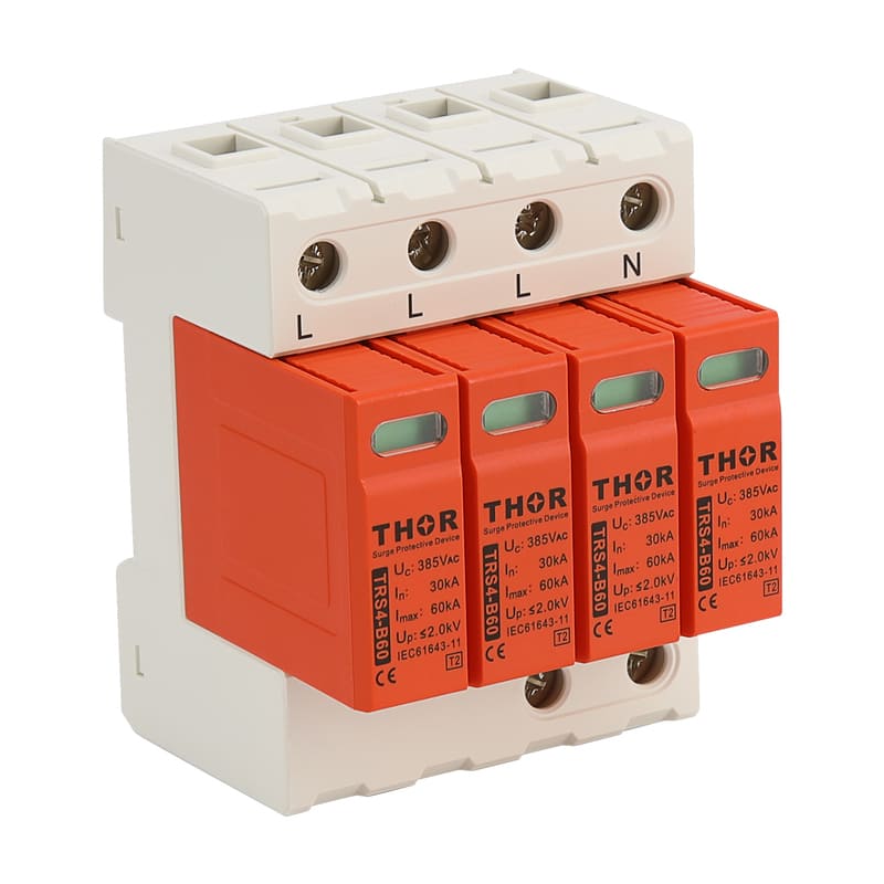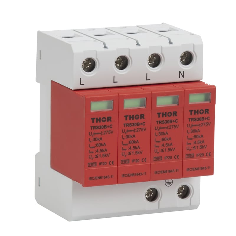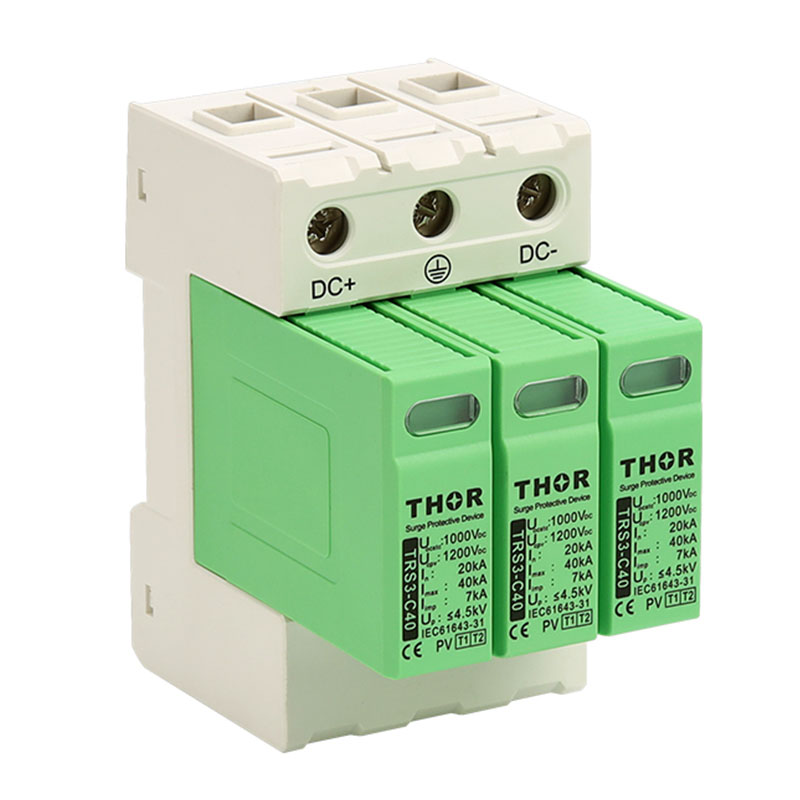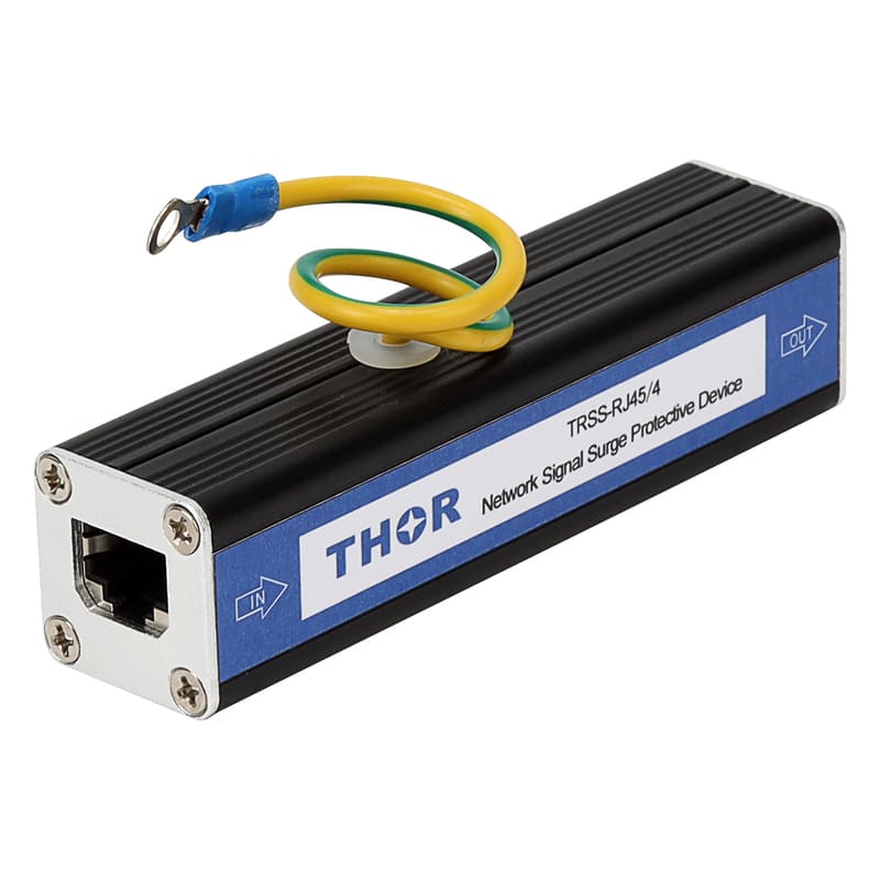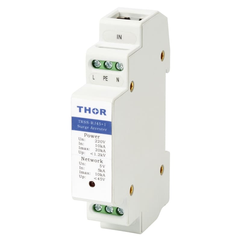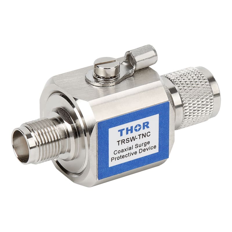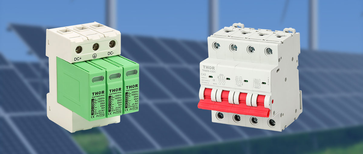
Figure 1 - 3-pole and 4-pole SPDs
Vulnerabilities of solar systems in electric disturbance
Due to their considerable size, investment and potential risks to human safety, solar/PV systems require careful planning and management.
Solar and PV systems are typically located far from residential areas, often with minimal protection for the facilities. Remote positioning, combined with their frequent placement among trees and mountains, increases their vulnerability to natural hazards such as lightning strikes and transient overvoltages.
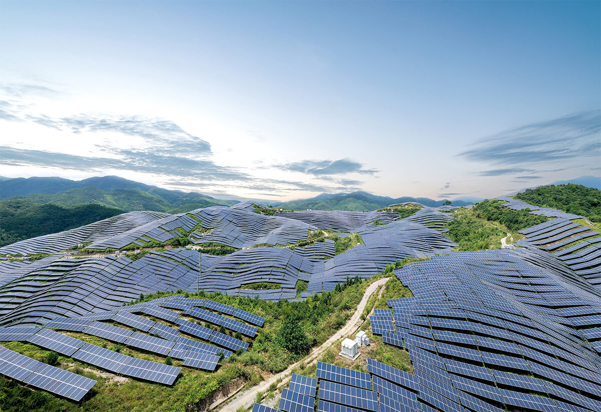
Figure 2 - PV farms in mountainous area
Solar systems can introduce harmonic distortions into the grid, causing overheating, increased transmission losses, and interference with communication systems, leading to equipment failure, reduced efficiency, and disruptions in power quality.
The lack of enclosure exposes solar panels to harsh conditions such as heavy rain and extreme temperatures, which can impact their efficiency and longevity. Combined with their exposure to natural hazards like hail, wildfires, and extreme weather conditions, solar plants are more vulnerable to damage and performance issues.
Potential consequences of leaving your PV farms and roof unprotected
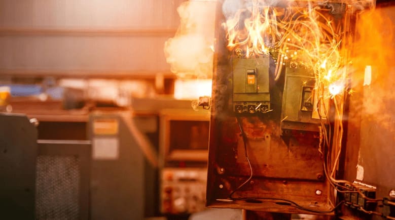
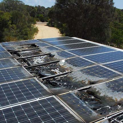
The most severe consequence of failing to protect your solar system from electric overvoltages is irreparable damage to your equipment. The lack of protection can cause the entire connected system to shut down completely. The inspection required to diagnose and repair the system can be time-consuming and troublesome.
 |
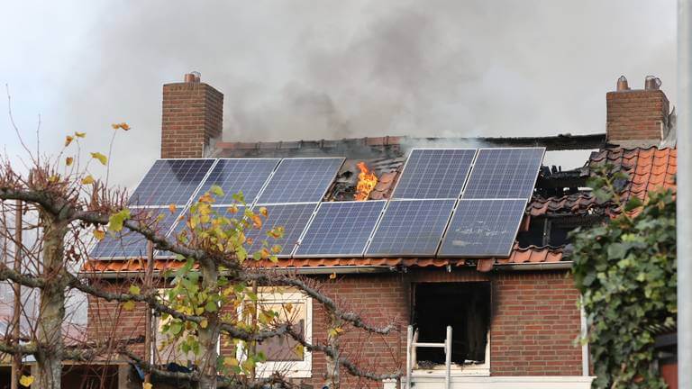 |
| Figure 3 - PV panel wiring fault | Figure 4 - PV roof electric hazards |
Even if you successfully identify the issue, the only viable solution may be to replace the entire series of affected equipment. This is because the internal structures of components, like semiconductors or photovoltaic cells, can be permanently compromised by excessive voltage spikes.
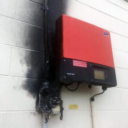
Figure 5 - PV inverter fault
Another important consideration is the integrity of the solar system as a whole. If components are damaged due to overvoltage, they may no longer be compatible with the rest of the system, even if partially repaired.
Additionally, attempting to repair damaged components might have implications for warranties and safety standards. Many manufacturers void warranties if the equipment is tampered with or repaired outside of authorized channels.
Difference between solar SPD and solar circuit breaker
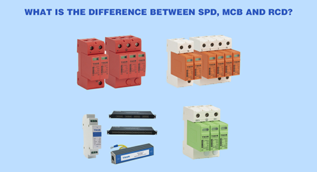
Both solar surge arresters and DC circuit breakers are designed to mitigate electric disturbances and protect PV systems from downtime and malfunction. However, they differ in their approach to handling overcurrent flow.
What is a Solar/DC/PV SPD?
A Solar/DC/PV SPD is designed to protect solar systems from voltage surges and spikes, typically caused by lightning strikes or grid fluctuations. It works by limiting the amplitude of overvoltages and diverting excess current to the ground.
Solar surge protective devices divert excess voltage away from sensitive components using devices like metal oxide varistors (MOVs) or gas discharge tubes (GDTs).
What is a solar circuit breaker?
Solar circuit breakers, often referred to as PV breakers, on the other hand, protect against overcurrent conditions by tripping and disconnecting power when necessary. They are reusable and typically installed on the DC side of PV systems. They detect excessive current flow, such as in the case of short circuits or overloads, and mechanically interrupt the circuit to prevent damage.
Typically installed in control panels or cabinets, PV circuit breakers safeguard circuits and connected equipment. In solar electrical systems, DC circuit breakers play a dual role. On the DC side, they prevent the overloading of solar panels, while on the AC side, they protect inverters and the building's electrical system. Additionally, circuit breakers can disconnect the solar PV system from the grid during power outages or maintenance.
A main loop with silver-plated contacts brings stable connections which is complemented by a closing mechanism powered by a magnet with a moving core, facilitating precise engagement. Overcurrent protection is provided by a device featuring a laminated armature and a spring-loaded lever to set the trip threshold. When excessive current is detected, the magnetic core triggers a rapid shutdown, safeguarding against damage.
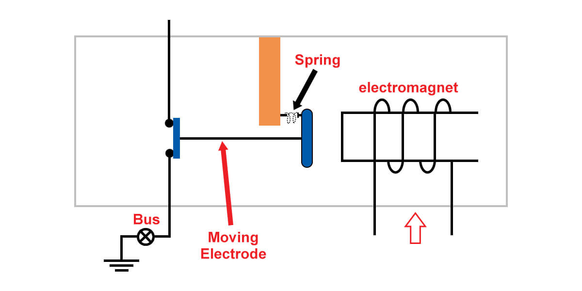
Figure 6 - DC circuit breaker working principle
Pros and Cons of Solar surge protection device vs. solar circuit breaker
Advantages:
● Response Time and Sensitivity: SPDs have a very fast response time dealing with transient overvoltages.
Solar circuit Breakers respond to overcurrent conditions, which may not be as immediate as the voltage spikes handled by SPDs.
● Installation Flexibility: SPDs can be installed at multiple points in a solar system for comprehensive protection.
DC Circuit Breakers are typically installed in electrical panels.
● Environmental Considerations: SPDs support the longevity of solar equipment, reducing waste.
Disadvantages:
● Price: SPDs can be more expensive than solar circuit breakers, especially when considering the need for multiple levels of protection in a solar system.
● System Integration and Complexity: While SPDs are specialized for surge protection, they require careful selection and installation to support compatibility with the solar system's voltage and surge current requirements. Solar circuit breakers, on the other hand, are simpler to integrate as they primarily protect against overcurrent conditions.
● Durability and Lifespan: SPDs may need replacement after absorbing important surges, whereas circuit breakers can often be reset without replacement.
● System Integration and Complexity: SPDs require careful integration to match the system's voltage and surge requirements, adding complexity.
Solar circuit Breakers are generally simpler to integrate into electrical systems.
How solar SPDs protect your PV systems
Surge protection devices (SPDs) are crucial for safeguarding photovoltaic (PV) systems from electrical surges caused by lightning, grid disturbances, or internal faults. Without SPDs, sensitive components like inverters and controllers can be damaged, leading to costly repairs and downtime.
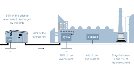
SPDs are categorized into types based on installation and protection level. Type 1 SPDs protect against direct lightning strikes at the grid connection, while Type 2 SPDs handle lower-energy surges at the distribution panel. Type 3 SPDs offer localized protection near components like inverters.
Key components include Metal Oxide Varistors (MOVs), Gas Discharge Tubes (GDTs), and Transient Voltage Suppression (TVS) Diodes, which work together to absorb and divert excess energy, ensuring system safety during electrical events.
How to select a proper surge protective device and DC circuit breaker for solar systems
Choosing the right surge protective device
To effectively protect your photovoltaic (PV) system from electrical surges, it's significant to select the right Surge Protection Device (SPD). The process involves considering several key factors. First, you need to know the lightning flash density in your area, which helps determine the level of protection required.
For general PV farm surge protection, both the DC and AC sides of the system should be installed with specific types of surge protection devices that include multiple SPDs on at least one side to offer layered protection.
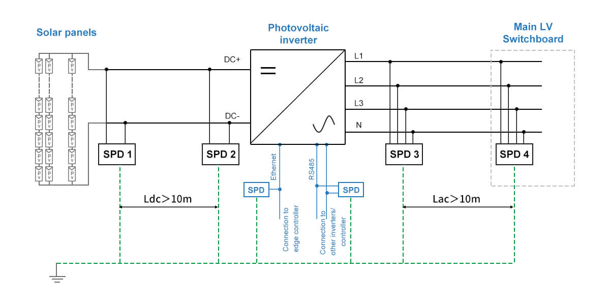
Figure 7 - Inverter surge protective device wiring diagram for layered protection
Considering the system size and the cable line length connected within the whole system, it is recommended to install layered SPD protection for DC PV systems.
Generally, you can install a DC PV surge arrester DC SPD T1+T2 TRS3-C40 close to the inverter if the cable length between the solar panels and the inverter is less than 10 meters. For longer cable lengths (over 10 meters), install an additional SPD near the solar panel boxes or combiner boxes.
DC T1+T2 TRS3-C40 surge suppressor
Install the T2 TRS2 AC SPD series after the inverter to protect the AC out. Consider installing a main surge protector at the service entrance to protect the entire electrical system.
AC Surge Protection Device T2 TRS2
Additionally, the SPD must be compatible with the system's operating temperature, voltage, and short circuit current rating. Understanding whether protection is needed against direct or indirect lightning strikes is also important, as well as knowing the nominal discharge current, which indicates the SPD's capacity to handle surges.
Choosing a Suitable Solar Circuit Breaker:
Ambient Temperature:
In photovoltaic systems, cables are often installed outdoors, where temperatures are typically higher than indoors. The increased ambient temperature reduces the ampacity of the circuit breaker, meaning it can handle less current than its nominal rating. Therefore, it's crucial to choose breakers that can operate effectively in these conditions.
Mutual Heating of Circuit Breakers:
In systems where multiple inverters input maximum current simultaneously, adjacent circuit breakers can heat up faster, which can lead to premature tripping. To mitigate the likelihood of this happening, large gaps should be maintained between individual solar circuit breakers to secure adequate heat dissipation. Alternatively, using a higher-rated circuit breaker or increasing the distance between breakers can prevent overheating.
Correction Factors for Heat Loss:
The technical data for solar circuit breakers often includes correction factors for heat loss. For instance, a row of nine devices might have a correction factor of 0.77. It means a 50A breaker would effectively behave like a 38.5A breaker (50A x 0.77). If the reduced capacity is insufficient, a higher-rated breaker should be used. Additionally, be sure that the connection cables have the appropriate current-carrying capacity to prevent overheating.
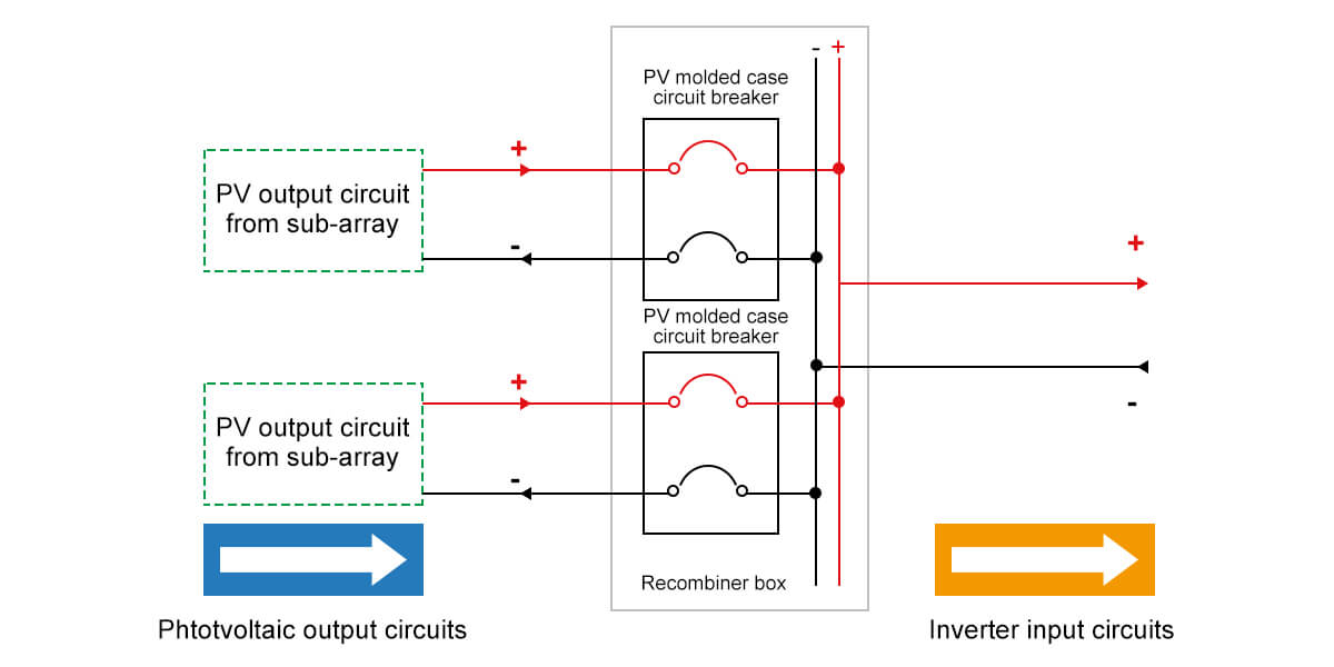
Figure 8 - NEC-defined PV output circuits with arrow-indicated protection
Additional Considerations
Cable Capacity: make sure the cables used can handle the derated current. If not, consider upgrading to a larger cross-section cable.
Breaker Spacing: Increasing the distance between solar circuit breakers can help dissipate heat more efficiently to prevent accidental tripping.
When selecting a circuit breaker for your solar panel system, it's essential to consider the specific requirements of your setup. Here are some general guidelines:
100-Watt Solar Panel: Typically requires a 15-amp circuit breaker.
200-Watt Solar Panel: Typically requires a 30-amp circuit breaker.
A general rule of thumb is to select a solar circuit breaker with a rating of 1.25 to 1.5 times the system's total wattage.
Photovoltaic (PV) circuit breakers are available in models rated for 600 and 1000Vdc, with options for either 80% or 100% capacity ratings. Understanding the distinction between these two ratings is crucial for optimizing your PV system's design.
80% Rated Circuit Breakers
For 80% rated circuit breakers, the total ampacity of the PV source circuits is calculated using a derating factor of 1.56 involving a multi-step process:
Short Circuit Current (Isc) Calculation: Start with the module's Isc.
First Derating: Multiply Isc by 1.25 to account for potential overcurrent conditions.
Second Derating: Multiply the result by 1.25 again to ensure safety margins.
Parallel Strings Adjustment: Finally, multiply by the number of strings in parallel.
This method enhances circuit breaker capability of handling the maximum expected current without overheating or failing prematurely. However, it requires oversizing the circuit breaker, which can lead to larger frame sizes, thicker conductors, and potentially larger enclosures, increasing costs and reducing system efficiency.
100% Rated Circuit Breakers
In contrast, 100% rated circuit breakers offer the advantage of utilizing their full nameplate capacity. The total ampacity of the PV source circuits is calculated using a simpler derating factor of 1.25:
Short Circuit Current (Isc) Calculation: Start with the module's Isc.
Derating: Multiply Isc by 1.25 to account for potential overcurrent conditions.
Parallel Strings Adjustment: Multiply the result by the number of strings in parallel.
The ability to use the full capacity of the DC circuit breaker means you can potentially reduce the required ampacity, frame size, conductor size, and even the enclosure size, which may result in cost savings and a more compact system design.
Installation and wiring of solar SPDs and PV breakers
For installations that include an external Lightning Protection System (LPS), the SPD requirements depend on the LPS class and the separation distance between the LPS and the PV system. The International Electrotechnical Commission (IEC) 62305-3 provides guidelines for these separation distances to support that the SPDs are installed correctly to provide optimal protection.
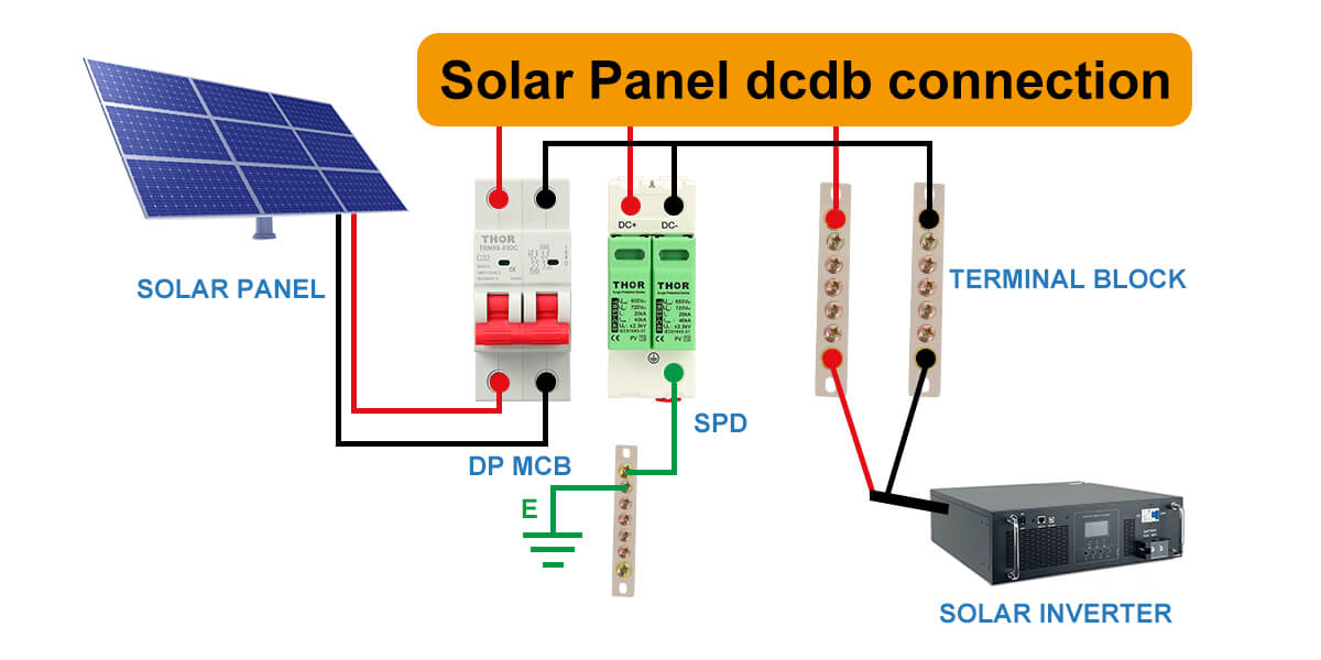
Figure 9 - Solar surge protection device wiring and installation
It's also important that the SPD's voltage protection level is at least 20% lower than the dielectric strength of the terminal equipment to prevent damage during surges. Furthermore, the SPD should have a short circuit withstand current greater than the solar array's short circuit current to handle potential faults safely.
Lightning strikes can cause significant damage to PV systems, particularly to the inverter, which is often the most expensive component. Therefore, proper installation of SPDs on both the AC and DC lines is essential to prevent such damage. On the DC side, PV systems have unique current and voltage characteristics that require specialized SPDs designed specifically for DC applications.
The chosen SPDs must be capable of handling the non-linear current and long-term arc persistence typical of PV systems. On the AC side, surge protection is equally important, and SPDs should be specifically designed for AC applications to offer optimal protection and longevity.
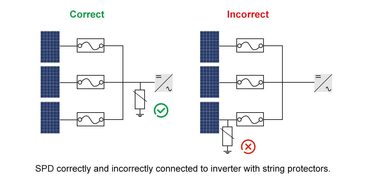
Figure 10 - SPD correctly and incorrectly connected to inverter with string protectors
When installing SPDs, it's crucial to follow specific guidelines. SPDs should always be installed upstream of the devices they are protecting. Key installation values include the maximum continuous operating voltage, which is the voltage at which the SPD activates, and the voltage protection level, which must be lower than the equipment's overvoltage category.
The nominal discharge current is also important, as it indicates the peak value of the waveform the SPD can withstand. For inverters with integrated fuse boxes, internal fuses should be bypassed, and external string fuses should be connected. SPDs should be mounted outside the inverter in a NEMA Type 3R enclosure or higher for outdoor applications, and SPD cables should be kept as short as possible (less than 2.5 meters) for efficient protection.
Finally, planning SPD combinations is necessary for inverters with multiple Maximum Power Point (MPP) trackers. Each input should have a reliable SPD, especially if it is fused with a string diode.
Calculating Solar Circuit Breakers in Solar PV Systems
Calculating the size of solar circuit breakers involves a straightforward process. The maximum continuous output current of the inverter is multiplied by a safety factor to determine the required breaker size. For example, if the inverter's maximum output current is 30A, you would multiply this by 1.25 to get 37.5A. This value is then rounded up to the nearest standard breaker size, typically resulting in a 40A breaker.

