Introduction
Surge protective devices (SPDs) have become a key part of electrical protection systems as infrastructure grows and safety awareness improves. However, even with the right SPD type in place, users still find that real-world performance often fails to meet expectations.
The truth is, choosing the right SPD goes beyond just its classification. Proper sizing is critical for performance and longevity, involving selection of the correct electrical parameter - like maximum discharge current, voltage protection level, and response time - as well as the enclosure fits the installation environment. For industrial and commercial projects, where power loads are heavier and distribution more complex, the size and fit of the SPD enclosure can directly affect both safety and ease of maintenance.
Failing to size SPDs correctly can lead to reduced protection, shortened device lifespan, and even safety risks. Understanding both the technical specifications and the physical demands of the installation site is essential to get the full value from your surge protection strategy.
Key electrical ratings to consider when sizing SPDs
Proper SPD sizing is a technical process that directly affects protection reliability and product longevity. Selecting the correct type is just the starting point - performance depends on how well the SPD's electrical parameters are matched to the actual characteristics of the system.
1.Nominal Voltage (Un):
Un indicates the standard operating voltage of the system (e.g., 230V for single-phase or 400V for three-phase systems). It defines the baseline for SPD design coordination. Selecting and sizing an SPD with a Un consistent with system voltage secure that the device remains within its normal operating range without triggering unwanted responses.
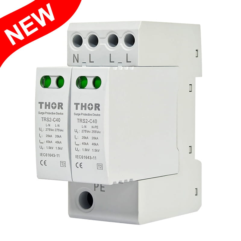
2.Maximum Continuous Operating Voltage (Uc):
Uc must always exceed the highest possible voltage the SPD will be exposed to during normal operation, including fluctuations and harmonics. In TT or IT systems with unstable voltage references, Uc often needs to be carefully up-sized. An SPD with undersized Uc leads to premature degradation; an oversized Uc compromises clamping performance.
3.Voltage Protection Level (Up):
Up defines the clamping threshold - the peak voltage that downstream equipment will experience during a surge. Lower Up ratings are essential for sensitive electronics and communication systems. When sizing SPDs near terminal loads or control panels, Up should be closely reviewed alongside insulation withstand levels of connected devices.
4.Nominal Discharge Current (In):
In refers to the current level the SPD can safely discharge repeatedly under standard 8/20 µs surge conditions. It reflects the SPD's durability under regular transient exposure, and must be matched to the system's surge environment.
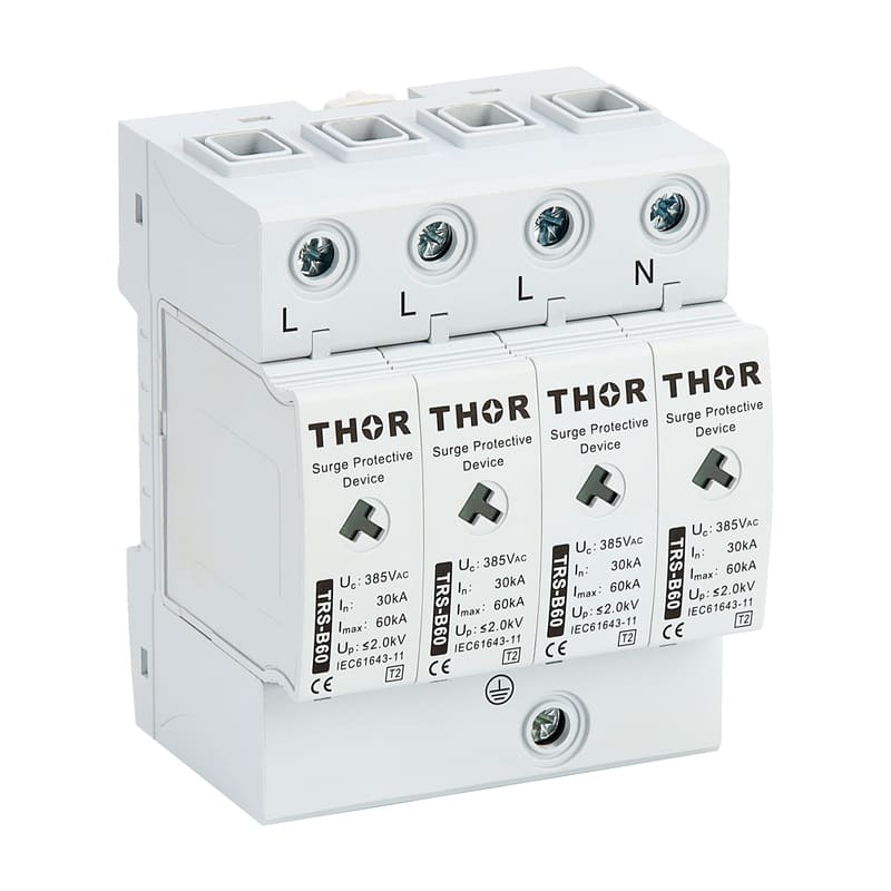
5.Maximum Discharge Current (Imax):
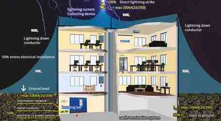
Imax represents the highest one-time impulse current the SPD can withstand without failure. In lightning protection zones (LPZ 0-1 boundaries), Imax must be sized based on the facility's lightning risk assessment and the installation's exposure level.
6.Short-Circuit Current Rating (SCCR):
SCCR specifies the maximum fault current the SPD can safely interrupt when installed in coordination with upstream overcurrent protection. For example, if installed in a distribution panel with a 25 kA breaker, the SPD's SCCR must meet or exceed this level. A mismatch creates a safety hazard and can violate installation codes.
7.Response Time (tr):
Response time is the delay between a surge occurrence and the SPD's clamping action. For most modern metal oxide varistor (MOV)-based SPDs, the rated response time should be below 25 ns. Fast response is critical for protection of sensitive electronics, particularly in control panels and data centers when sizing SPDs. While response time alone doesn't define effectiveness, it contributes to the overall protective performance in high-frequency surges.
Mechanical enclosure sizing considerations for SPD selection
1.IEC 61643 Compliance
A well-designed SPD enclosure should comply with IEC 61643-11, which governs performance and safety requirements. Though IEC does not enforce fixed physical dimensions, it specifies spacing and clearance requirements for internal components and terminals.
For example, SPDs must maintain minimum clearances between live parts and enclosure walls (usually≥10 mm for certain voltage classes) to avoid flashover or tracking. The enclosure must also accommodate safe cable bending radii and meet overvoltage category separation.
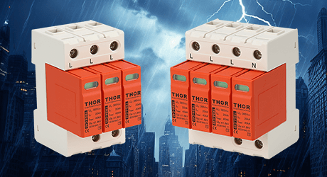
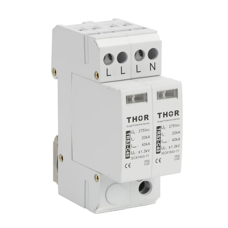
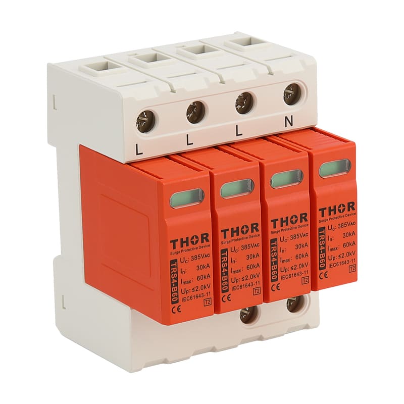
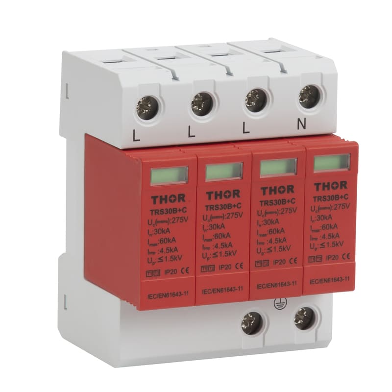
Standard DIN-rail mounted SPDs typically follow modular widths of 18 mm, 36 mm, 54 mm, or more, depending on the number of poles and built-in disconnection modules. A 4P SPD for three-phase TN-S systems, for instance, usually requires at least 72 mm of width and 90–120 mm of height and depth.
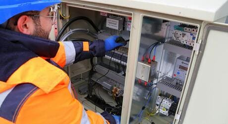
2.Fit for Distribution Panels
SPD enclosures must be compatible with the target distribution box or panelboard layout, whether it's a surface-mounted load center or a flush-mounted industrial cabinet. In retrofits, space may already be limited, so compact SPD modules that fit neatly alongside other DIN-rail components without requiring custom enclosures are ideal. It's critical to leave adequate space above and below the SPD for terminal access and heat dissipation.
If SPDs are used in main distribution boards (MDBs), some installers prefer panel-mount SPDs with screw terminals, while modular DIN-rail units are common in final distribution boards. Choosing the correct form factor avoids crowding and simplifies cabling.
3.DIN-Rail Mount and Pluggable Module
Most modern SPDs are DIN-rail mountable, streamlining installation and replacement. Enclosures should offer mechanical latching systems that hold firmly against vibration or thermal expansion. For systems where ongoing maintenance is required, pluggable SPD modules allow the protection cartridge to be replaced without disconnecting wiring. Din-rail module design is crucial in SPD selection and sizing especially for facilities that demand low downtime and easy serviceability.
4.Ingress Protection (IP) Rating
The IP rating of the SPD enclosure determines its suitability for indoor or outdoor use. For indoor installations, IP20 or IP30 is typically sufficient, offering basic protection against accidental contact. For harsh environments - including dusty workshops or outdoor substations - higher ratings like IP 65 or IP 67 are essential to guard against water ingress, corrosion, and particulate contamination. Outdoor SPDs may also require UV-resistant and flame-retardant plastic or coated metal housings.
5.Other Practical SPD Sizing Considerations
Labeling and Indicators: A good enclosure design provides visible access to status indicators (window or LED) and laser-etched labels for part number, voltage class, and connection diagrams.
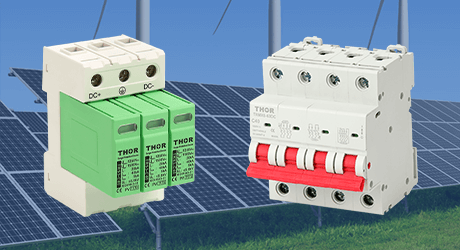
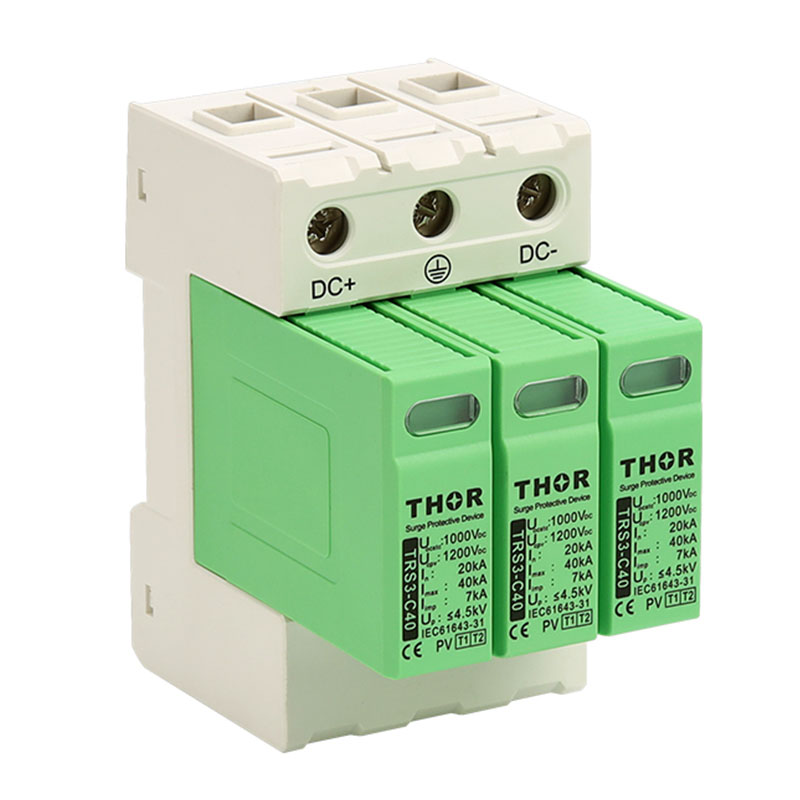
Color Coding: Some manufacturers use different enclosure colors for AC and DC SPDs or for different voltage classes, which aids in quick identification during inspections.
Environmental Ratings: For coastal or chemical plant installations, enclosures may require salt spray resistance or anti-condensation features.
Thermal and environment considerations
When selecting and sizing surge protective devices (SPDs), thermal and environmental considerations are essential to maintain long-term functionality and reliability.
SPDs function to absorb and dissipate excess energy during power surges, which can generate heat in the process. If the device is exposed to temperatures beyond its rated range, typically between -40°C to +80°C for many models, the internal components may degrade, causing early failure. In extreme cases, temperatures exceeding limits can result in the SPD's complete breakdown, leading to an inability to protect the electrical system effectively.
Thermal management is crucial in size of SPDs in environments with high ambient temperatures, as sustained high heat can lead to a decrease in the life expectancy of surge protective devices. For example, studies have shown that for every 10°C increase in operating temperature above the recommended limit, the lifetime of an SPD may be reduced by up to 50%.
Proper ventilation and heat dissipation are equally significant to maintain optimal operating conditions, particularly for industrial applications where high thermal loads are typical. Depending on the device, heat sinks or external cooling systems may be necessary to maintain an acceptable thermal balance.
Environmental conditions, particularly humidity and particulate contamination, also impact the SPD performance. High humidity can accelerate corrosion, while dust and other contaminants can obstruct air flow, increasing heat retention.
Standards and regulations for selection and sizing of SPDs
While IEC 61643-11 defines performance testing and classification of SPDs, IEC 61643-12 serves as the guiding standard for selection, application, and coordination size of SPDs within low-voltage power systems. It provides important guidelines for how to size and install SPDs based on real-world system conditions, making it particularly critical for engineering applications.
In accordance with IEC 61643-12, proper selection and size of SPDs go beyond discharge capacity and protection level. Certification standards emphasize that SPDs must also demonstrate durability under temporary overvoltage (TOV) conditions, and the ability to continuously operate without degradation in a variety of power system configurations.
1.TOV Withstand Requirements (UTOV)
IEC 60364-4-44:2007, referenced in IEC 61643-12, outlines expected TOV levels that can occur due to system disturbances such as:
● Loss of the neutral conductor
● Accidental grounding of a phase conductor in IT systems
● Short circuits between line and neutral
● Faults in high-voltage systems transferred into the low-voltage network
These fault conditions can result in temporary but severe voltage rises across different conductor combinations. For example:
● In TT and IT systems, phase-to-earth voltages may rise up to U₀+ 1200 V for durations up to 5 seconds, or U₀+ 250 V for durations >5 seconds.
● In low-voltage systems, neutral loss can cause the phase-to-neutral voltage to rise to √3 × U₀, while phase-to-earth TOVs in IT systems may also reach √3 × U₀.
● Between phase and neutral, systems may experience up to 1.45 × U₀for short periods (≤5 s).
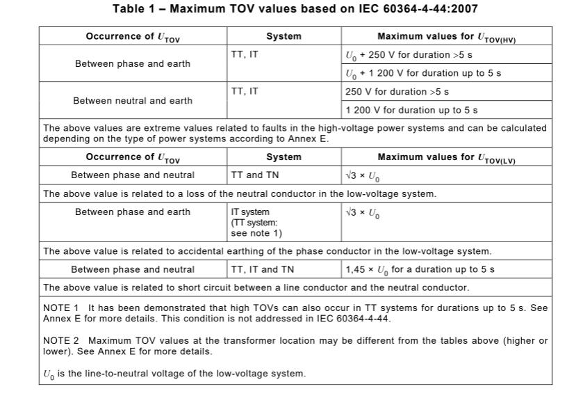
Table 1 of IEC 61643-12
An SPD installed in such a system must have a TOV withstand rating (UTOV) suitable for these fault levels. If the SPD disconnects or fails under these conditions, the system is left unprotected at the very moment protection is most needed. Therefore, compliance with TOV withstand requirements is a critical part of SPD certification, and should be verified for the specific system type (TN, TT, IT) and known fault scenarios.
2.Continuous Operating Voltage (Uc) Selection
While TOV ratings relate to short-term fault events, Uc defines the maximum RMS voltage the SPD can endure continuously without degradation. An undersized Uc can result in premature aging of the SPD, leakage current increase, nuisance tripping, or even thermal runaway.
Table 4 of IEC 61643-12 specifies the minimum recommended Uc values based on both the system configuration and the conductor pair the SPD is connected across. For instance:
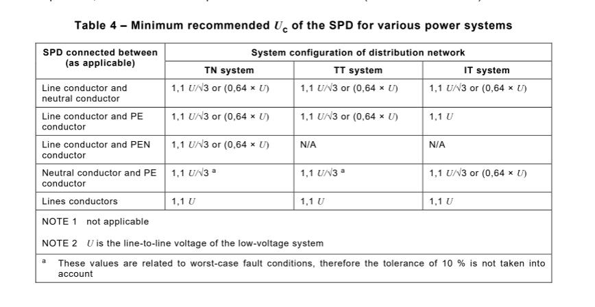
Table 4 of IEC 61643-12
For an SPD connected between line and neutral in a TN system, the minimum Uc is 1.1 × U₀/√3, which is approximately 0.64 × U, where U is the line-to-line voltage.
For line-to-PE connections in IT systems, the Uc must be at least 1.1 × U, since the full system voltage can appear between line and PE under fault conditions.
For line-to-line SPDs in all systems, 1.1×U is the baseline minimum.
These values reflect worst-case design conditions and do not include the standard 10% overvoltage tolerance, which is an important distinction. In practice, engineers must ensure that Uc is high enough to accommodate normal voltage fluctuations and minor overvoltages without triggering the protection mechanism unnecessarily.
3.Certification Implications
SPD manufacturers are required to declare the UTOV and Uc values as part of the certification process, often based on standardized testing according to IEC 61643-11. Proper SPD sizing must match these certified ratings with:
The earthing system configuration (TN, TT, IT)
The point of connection (line-neutral, line-PE, etc.)
The network voltage level
The possible fault scenarios, including TOV exposure and their expected durations
Failure to align these parameters can lead to non-compliance, compromised protection, or even hazards such as fire or electric shock.
Potential consequences of oversizing and undersizing SPDs
Oversizing surge protection devices
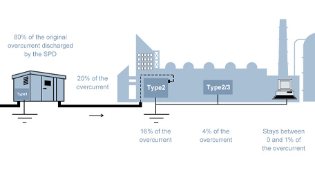
In the scenario where a correctly sized SPD is rated at 12.5 kA and is replaced with a 20 kA SPD, the device will not fail to operate simply because it's oversized. However, there are nuanced implications to consider, particularly with regard to voltage clamping levels and the protection of sensitive equipment.
SPD Action and Voltage Clamping SPDs activate based on voltage, not current. Even with a surge as low as 1 kA, an SPD rated at 20 kA will trigger as long as the surge voltage exceeds its clamping threshold (Up). In this sense, an oversized SPD still performs its intended function - intercepting surges.
The key issue with oversizing arises from the voltage protection level (Up). SPDs with higher surge current ratings, such as 20 kA, may have a higher clamping voltage compared to smaller, correctly-sized SPDs. For example, a 12.5 kA SPD may clamp surges at 1.5 kV, while a 20 kA SPD could clamp at 2.0 kV. The increased clamping voltage means that more residual voltage might reach sensitive equipment, which can be damaging over time. This becomes a big concern, especially for systems with high-precision electronics or communication devices that require very low voltage tolerances.
Oversizing does not mean the SPD will fail to activate, but it could result in a less effective protection strategy. The primary drawback is the potential for a higher clamping voltage, which might not be low enough to protect vulnerable devices.
Undersizing surge protection devices
Undersizing typically refers to selecting an SPD with a lower In or Imax than the expected surge environment. For example, installing a 5 kA SPD in a zone with potential exposure to 10 kA surges can result in the device failing during transient events.
The metal oxide varistors (MOVs) or gas discharge tubes (GDTs) inside may degrade rapidly, leading to increased leakage current, thermal damage, or complete breakdown. Worse, it may give a false sense of protection while silently failing.