Introduction
A steady electrical supply keeps modern industry running, but it’s vulnerable. Lightning strikes or sudden internal switching can send dangerous voltage spikes through the system. The spikes don’t just damage equipment—they can shut down operations and create real safety risks. To protect against it from happening, we rely on surge arresters and lightning arresters.
But people often mix up these two terms, and it may have lead to the wrong kind of protection. Yes, they both shield against overvoltage, but each deals with a different problem. Knowing exactly what each device does matters. That’s how you build an electrical protection system that actually works—one that keeps operations moving and equipment safe for the long run.
What is a surge arrester?
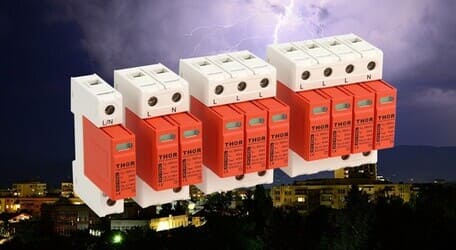
Surge arresters, known more formally as Surge Protection Devices, is an protective equipment designed to protect electrical and electronic appliances from transient overvoltages.
Its primary function is to shield sensitive internal assets from threats of surge energy strikes. While indirect lightning strikes impose higher energy impact, the majority of surges are generated internally by the normal operation of motors, pumps, HVAC systems, and other equipment. The frequent, low-magnitude events cause cumulative stress and degradation that can result in the premature failure of microprocessors and control circuits.
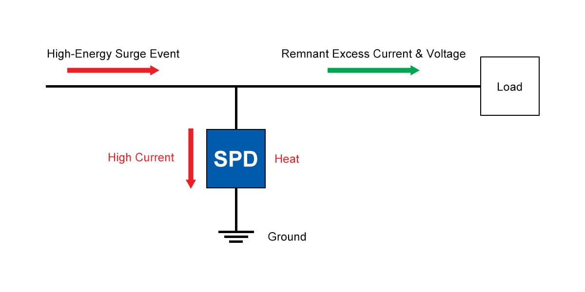
Figure 1 - Surge arrester working principle
The SPD is installed within electrical panel boards, and close to critical loads, SPD performance occurs via non-linear components, specifically Metal Oxide Varistors (MOVs). Under normal voltage conditions, the MOV's high impedance leaves it invisible to the circuit. When the voltage transient exceeds the MOV's impulse rating, the MOV's impedance drops to a low level within micro-seconds providing a low impedance path to ground for the hazardous surge current.
This action clamped the voltage down to a safe level to the attached equipment. After the surge transient energy has passed, the SPD system is automatically reset and provided surge over voltage protection for the next event.
What is a lightning arrester?
A lightning arrester is a rugged protective device built to withstand direct lightning strikes. Unlike surge protection devices (SPDs), which protect specific areas inside a building, lightning arresters are almost always installed outdoors in high - voltage settings.
The lightning arrester provides protection to the insulation and conductor of the electrical power system, which can be millions of volts and thousands of amperes in a direct hit.
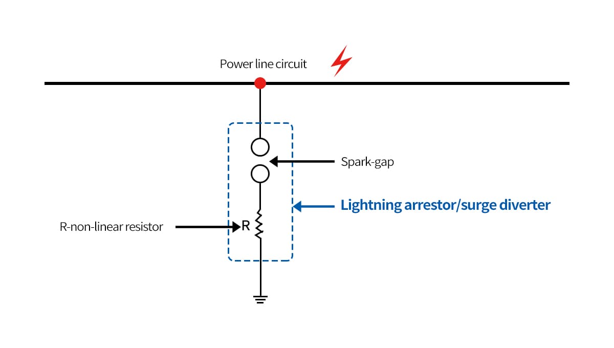
Figure 2 - Lightning arrester working principle
A lightning arrester is installed between a high-voltage line and the earth to protect electrical equipment from lightning-induced overvoltages. Most modern arresters contain metal oxide varistor (MOV) blocks that act as open circuits under normal conditions. When lightning strikes, the extreme voltage causes the MOV blocks to conduct and provide a low-resistance path to safely divert surge current to ground.
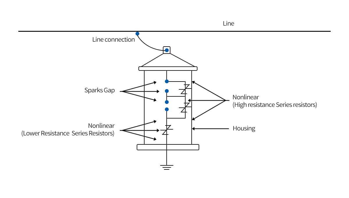
Figure 3 - Lightning arrester interior structure
lightning arresters are designed to divert large, catastrophic energy rather than precisely regulate voltage. They form the first line of defense for the power grid by providing a rapid, high-capacity path to ground during surges.
Surge arrester vs. lightning arrester: key differences
While both devices manage overvoltage, their fundamental differences lie in application, energy handling, and protective philosophy. A lightning arrester is an infrastructure-level device installed externally on high-voltage systems. Its sole purpose is to handle the immense, high-current impulses from direct lightning strikes, diverting tens of thousands of amperes to prevent catastrophic flashover and equipment destruction. Its primary performance metric is its ability to survive and channel massive amounts of energy.
A surge arrester (SPD), conversely, is an equipment-level protection device installed internally within a facility's low-voltage distribution system. It is engineered to protect sensitive electronics from a much wider range of lower-energy transient events, including internally generated switching surges and indirect lightning-induced surges.
The critical performance metric for an SPD is its Voltage Protection Level (VPL)—the residual voltage it “lets through” to the protected equipment. While a lightning arrester may let through thousands of volts after diverting a strike, an effective SPD will clamp this voltage down to a few hundred volts, a level safe for modern electronics.
|
Feature |
Lightning Arrester |
Surge Arrester (SPD) |
|
Primary Role |
Direct lightning strike diversion |
Transient overvoltage clamping |
|
Application |
High-Voltage (Utility Grid) |
Low-Voltage (Internal Facility) |
|
Installation |
External (Towers, Substations) |
Internal (Panels, Near Equipment) |
|
Energy Handling |
Extremely High (10s of kA) |
Moderate to High |
|
Key Metric |
Survivability & Current Rating |
Voltage Protection Level (VPL) |
|
Protective Philosophy |
Bulk Energy Diversion |
Precise Voltage Limiting |
Table 1 - Lightning arrester and surge arrester comparison table
How they work in the overall overvoltage protection scheme
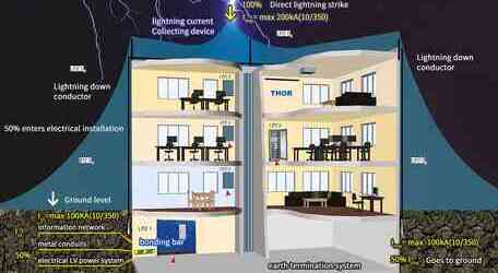
A comprehensive protection strategy does not treat these devices as separate solutions but integrates them into a coordinated, multi-layered defense system, often explained by the Lightning Protection Zone (LPZ) concept. This approach creates a series of barriers that systematically reduce the overvoltage energy as it moves from outside a facility to the sensitive equipment within.
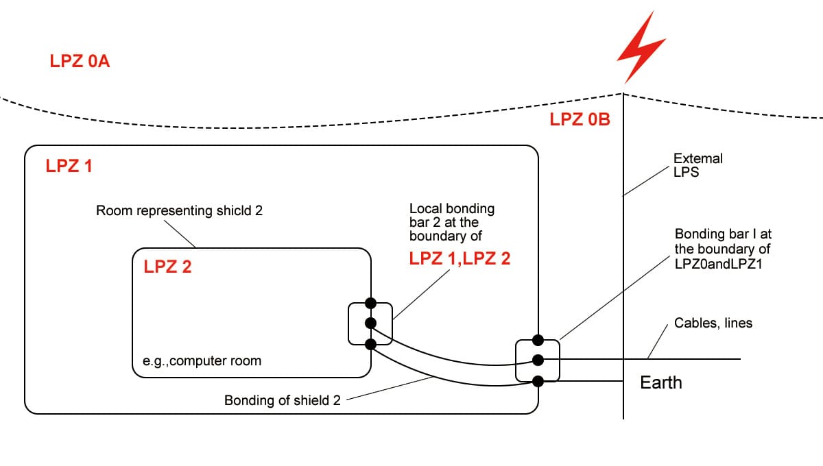
Figure 4 - Lightning protection zone within a structure or building
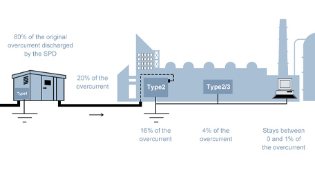
The first layer, in the external environment (LPZ 0), is the lightning arrester itself (often part of a larger lightning protection system). It intercepts the direct strike and diverts the bulk of its catastrophic current to the earth. However, a significant portion of this energy still enters the building through power conductors.
At the service entrance where power enters the building (the boundary of LPZ 1), a robust Type 1 SPD is installed. This device is specifically designed to handle the high-energy residual current from an external lightning event. From there, Type 2 SPDs are installed in downstream distribution panels (LPZ 2).
These devices further reduce the voltage and protect against internally generated surges created by machinery within the facility. For the most critical and sensitive electronics like computers or PLCs, Type 3 SPDs are used at the point of connection (LPZ 3), providing a final clamping stage that ensures the voltage reaching the equipment is well below its damage threshold.
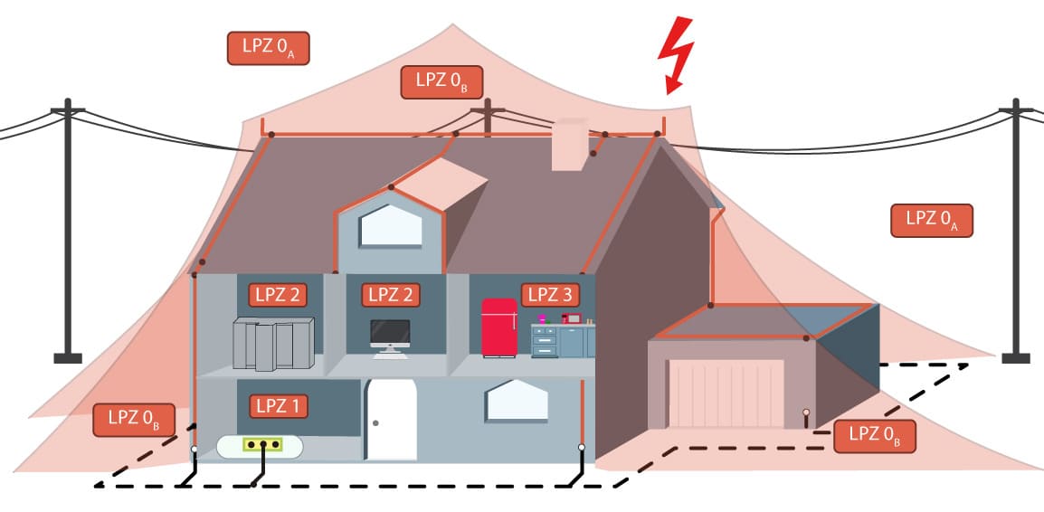
Figure 5 - Lightning protection zone in a building
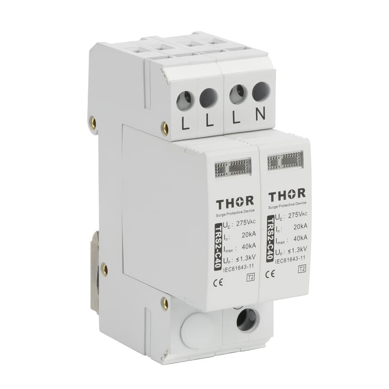
How to select the right surge arresters?
● 1. Selection based on Installation Point (SPD Type)
The location within the electrical installation dictates the required SPD Type, in accordance with the lightning protection zone (LPZ) concept.
Type 1 SPD: Installed at the point of entry of the electrical installation (e.g., main distribution board). Type 1 SPDs are designed to discharge high-energy partial lightning currents and surges. They are the primary protection barrier, typically used at the boundary of LPZ 0A and LPZ 1.
Type 2 SPD: Installed in sub-distribution boards or near terminal equipment. They protect against residual overvoltages that have passed the Type 1 arrester and against internally generated surges. Type 2 surge arresters are typically used at the boundary of LPZ 1 and LPZ 2 and higher.
2.Key Performance Parameters
Nominal Discharge Current (In): In indicates the peak current value that an SPD can withstand for a specified number of surges without performance degradation. It is a key indicator of the device's operational performance and service life.
Voltage Protection Level (Up): Up represents the maximum residual voltage that is passed to the protected equipment during a surge event. It is the most critical parameter for equipment protection. A lower Up value provides better protection for sensitive electronics.
 |
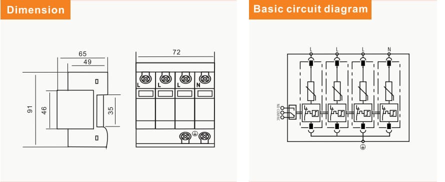 |
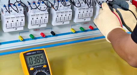
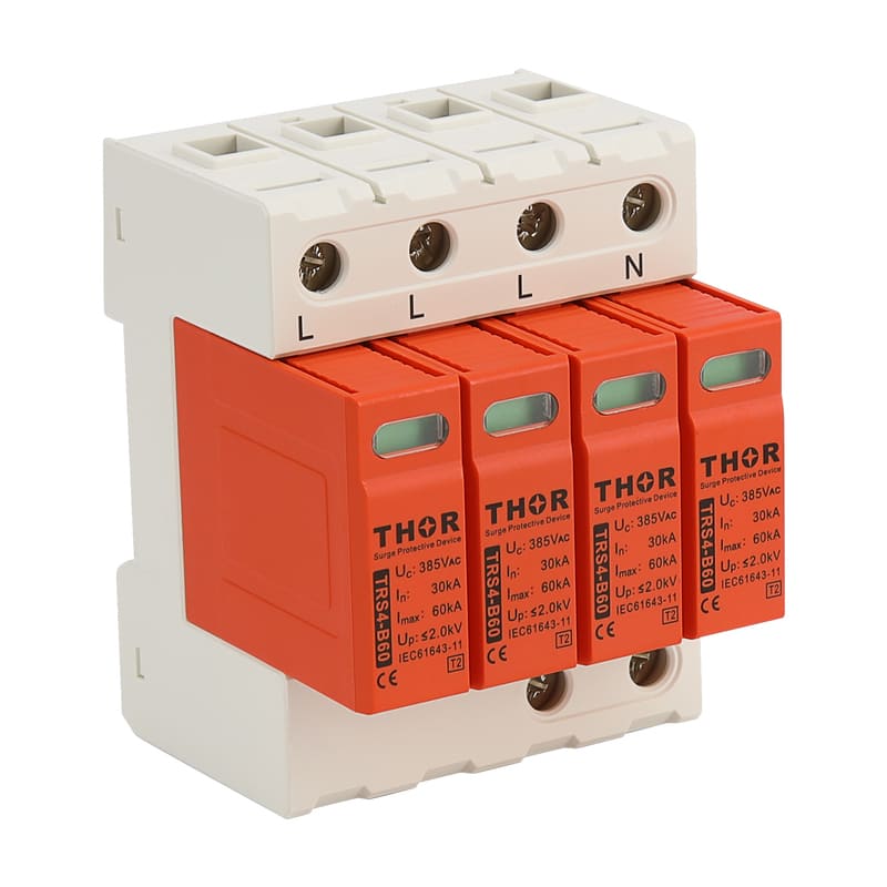
TRS 4 series type 2 surge protection device
For instance, our TRS-4 Type 2 SPD series is available with In ratings from 5 kA to 30 kA and a Up of ≤ 0.7 kV, which offers a wide range of applicable situations where you can get reliable protection for residential, commercial, or light industrial power systems.
| Parameter/Type | TRS4-D10 | TRS4-D20 | TRS4-C40 | TRS4-B60 | |
|---|---|---|---|---|---|
| Nominal volatge | Un | 230V AC | |||
| Maximum operating voltage | Uc | 275V AC | |||
| Nominal discharge current (8/20µs) | In | 5kA | 10kA | 20kA | 30kA |
| Maximum discharge current (8/20µs) | Imax | 10kA | 20kA | 40kA | 60kA |
| Voltage protection level | Up | ≤0,7kV | ≤1,0kV | ≤1,3kV | ≤1,5kV |
Key technical ratings for TRS-4 series
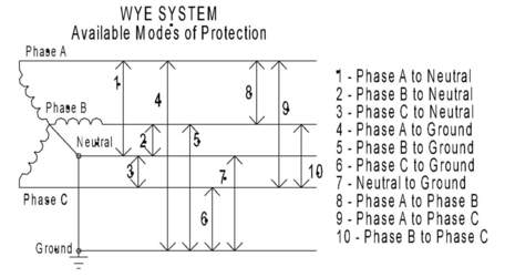
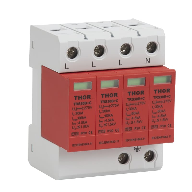
3.Configuration for Three-Phase Systems (3+1 or 4+0)
The selection of the circuit configuration is determined by the grounding system of the electrical network.
TN-S System: In a TN-S system, both 4+0 and 3+1 protection configurations are suitable options.
The 3+1 configuration, however, often provides enhanced protection because it incorporates a high-capacity N-PE protection module—usually a Gas Discharge Tube—that helps handle fault conditions more effectively.
TT System: In a TT system, the 3+1 configuration is mandatory. Unlike TN systems, where Neutral (N) and Protective Earth (PE) share a common grounding point, the TT system uses separate earth electrodes for the supply and the installation. Therefore, the resistance and potential of each electrode can differ significantly. During an earth fault or surge event, current flowing through the Neutral grounding path can cause a voltage rise relative to the local PE electrode, resulting in a considerable potential difference between N and PE.
In a 4+0 SPD configuration, voltage may appear on the PE line during faults or MOV failures, posing an electric shock hazard. The 3+1 configuration eliminates the risk with its N-PE Gas Discharge Tube (GDT) remained isolated under normal conditions and only conducts during a surge.
4.Additional Functional Parameters
For specific applications, other features should be considered:
IP Rating: Specifies the degree of protection against ingress of solid objects (dust) and liquids (water), essential for devices installed in harsh industrial environments.
Remote Signaling Contact: Provides a floating contact to transmit the operational status of the SPD to a central monitoring system (BMS or PLC), allowing for proactive maintenance.
Pluggable Modules: Allows for the quick and cost-effective replacement of individual protection modules at their end-of-life without disconnecting the base of the device from the wiring.
Conclusion
Surge arresters and lightning arresters are not interchangeable and should be thought of as part of a complete protection scheme. Lightning arresters provide the heavy-duty, exterior protection in the event of high-energy direct hits to the power grid, while surge arresters (SPDs) provide the critical, fine-tuned, interior protection that protects sensitive electronic equipment from diverse damaging transients.