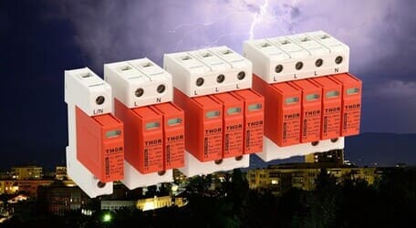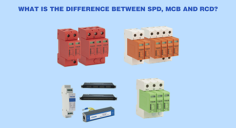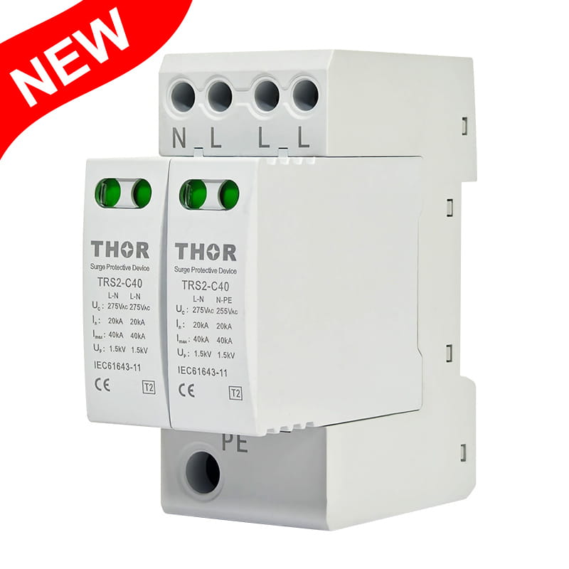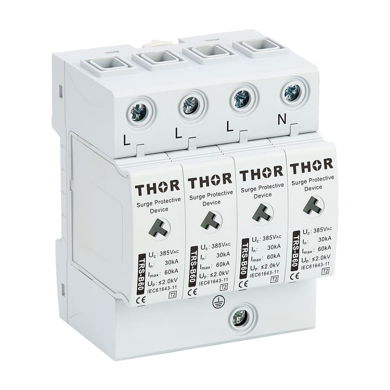
An SPD thermal disconnector removes an overheating protection path from service under its declared operating conditions. That action limits continued heating, but it does not repair the surge protective device or restore protection. The distribution circuit can remain energised after disconnection, while the affected path no longer provides surge protection.
For maintenance teams, the practical response is to treat a fault indication as a call to inspect and replace the correct module or device. For buyers, the important questions concern declared disconnection behaviour, status indication, replacement method, and coordination with upstream protection.
How an SPD thermal disconnector responds to heat
An SPD thermal disconnector is an internal safety function in an MOV-based low-voltage power SPD. When abnormal heating reaches the product's operating condition, the disconnector opens the affected protection path. The load circuit can remain energised, but that disconnected path no longer provides surge protection, so the specified SPD module or complete device must be replaced.
A metal oxide varistor, or MOV, normally conducts very little current at the continuous operating voltage. During a short surge, it conducts and limits the voltage presented to downstream equipment. Ageing, repeated electrical stress, or an abnormal sustained voltage can raise leakage current. Rising leakage increases dissipated power and component temperature; further heating can raise leakage again, creating the positive feedback known as thermal runaway.
Many MOV-based designs use a heat-responsive joint to restrain a spring-loaded contact. Heat conducted from the MOV changes or releases the joint, and stored mechanical force separates the electrical contact to remove that MOV path from service. Designs can use different materials, linkages, or combined disconnector functions, so this is a general operating example rather than a description of every SPD or confirmation of Thor's internal design.
The thermal disconnector responds to that heating condition by separating the affected MOV path from the circuit. Its purpose is isolation, not continued operation. The exact operating temperature, time, and sequence depend on the SPD design and its declared test evidence; there is no universal trip value that can be applied to every product.
Figure 1 shows a Thor pluggable SPD module opened to reveal the MOV block and mechanical assembly. The photograph supports the module construction only; it does not establish a particular thermal-disconnector design or operating threshold.
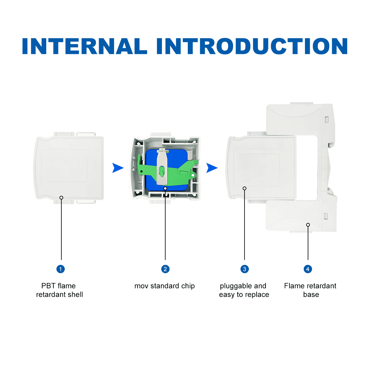
Figure 1 — Internal view of a Thor pluggable SPD module, showing the MOV block, mechanical assembly, removable module, and base.
Four parts that do different jobs
An MOV, a thermal disconnector, a status indicator, and upstream protection are related, but they are not interchangeable. Reading each part by its declared role prevents two common mistakes: assuming that a healthy breaker means the SPD is healthy, or assuming that a red indicator explains the internal cause of failure.
|
Part |
Main job |
What it does not prove or replace |
|
MOV |
Conducts surge current and limits transient voltage. |
It is not intended to carry abnormal power-frequency current indefinitely. |
|
SPD thermal disconnector |
Isolates an overheating MOV protection path under its declared operating conditions. |
It does not restore surge protection after operation. |
|
Status indicator |
Shows the manufacturer's declared service or fault state. |
It does not measure temperature or identify the root cause. |
|
Upstream fuse or circuit breaker |
Provides the declared fault-current protection and installation coordination for the circuit. |
It does not perform the same local thermal-sensing role inside the SPD. |
The distinction matters because degradation-related heating and a larger fault current are different operating conditions. In their 2011 paper on SPD disconnectors, Atsushi Sato, Nobuyuki Morii, and Hidetaka Sato describe a thermal protection function built into voltage-clamping MOV SPDs and a current-disconnection function used when excess voltage or degradation produces a large fault current. Product instructions must still define the required upstream protection and coordination for the specific installation.
Figure 2 follows these roles through one simplified sequence. It shows an MOV progressing from normal service to abnormal heating, isolation, a visible fault state, and replacement. The sequence is explanatory rather than a universal timing or construction diagram.
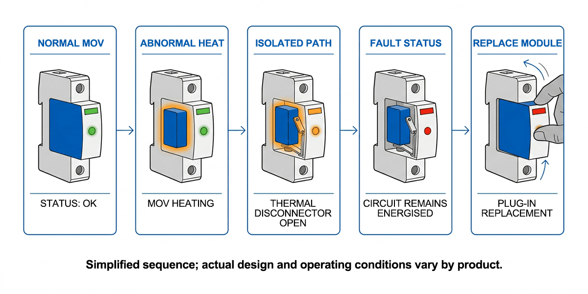
Figure 2 — Simplified sequence from normal MOV operation through abnormal heating, isolation, fault indication, and replacement.
What a red SPD indicator does and does not mean
A red status window should be read according to the manufacturer's instructions. On an SPD with red visual fault indication, it reports a declared fault or end-of-life state and signals that maintenance is required. It does not show the MOV temperature, identify the event that caused the change, or prove that one particular internal component operated.
Do not assume the SPD is serviceable simply because the connected circuit still has power. A disconnected protection path can leave the load energised but without the intended surge protection. The maintenance response is to follow site isolation procedures, inspect the SPD and surrounding installation, and replace the specified module or complete device.
Before returning the installation to service, check for visible heat damage, loose terminations, incorrect system voltage, or another condition identified by the product instructions. Replacing a pluggable module restores the hardware only when the correct replacement is fitted, the base and wiring remain suitable, and coordination is correct. Remote signalling can help maintenance teams detect the status change, but it does not diagnose the cause.
Five checks before you approve an SPD
Figure 3 turns the component discussion into a short approval checklist. Ask the supplier for product-specific evidence rather than accepting a general statement that the device has “thermal protection.”
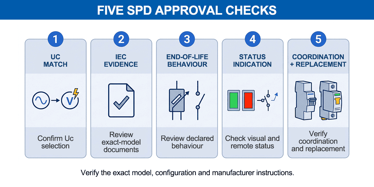
Figure 3 — Five checks for selecting an MOV-based SPD with clear disconnection and status information, upstream coordination, plus replacement instructions.
1. Correct continuous operating voltage: Confirm that Uc suits the power system, voltage tolerance, earthing arrangement, and application. An unsuitable selection can expose the MOV to excessive steady-state stress.
2. Applicable test documentation: Review the report or certificate for the exact model and configuration. IEC 61643-11 provides requirements and test methods for SPDs connected to AC low-voltage power systems; a reference to the standard alone is not model-level evidence.
3. Declared end-of-life behaviour: Check how the manufacturer describes disconnection, fault indication, and the condition of the protected circuit after the SPD changes state.
4. Visible and remote indication: Confirm that the status can be checked during routine maintenance and whether a remote contact is needed for unattended panels.
5. Coordination and replacement: Verify the specified upstream protective device, available fault-current conditions, wiring instructions, and the correct replacement module or complete SPD.
FAQ
Can an SPD thermal disconnector prevent every hazardous failure?
No single component covers every possible failure mode. An SPD thermal disconnector's performance depends on the device design, the fault condition, installation coordination, and the product's verified requirements and tests. Correct selection and upstream protection still matter.
Will the SPD still protect after thermal disconnection?
The affected path no longer provides surge protection after it has been disconnected. The load circuit may remain energised, which can hide the loss of protection unless the visual window or remote status is checked.
Can a circuit breaker replace an SPD thermal disconnector?
No. A circuit breaker or fuse and the local thermal disconnector respond to different conditions and operating ranges. Use the upstream protective device stated by the SPD manufacturer instead of treating one device as a substitute for the other.
What exactly does a red SPD window mean?
It means the SPD has reached the red status defined in its instructions, commonly a fault or end-of-life condition requiring replacement. The window alone does not reveal temperature, degradation history, or the exact internal event, so inspection remains necessary.
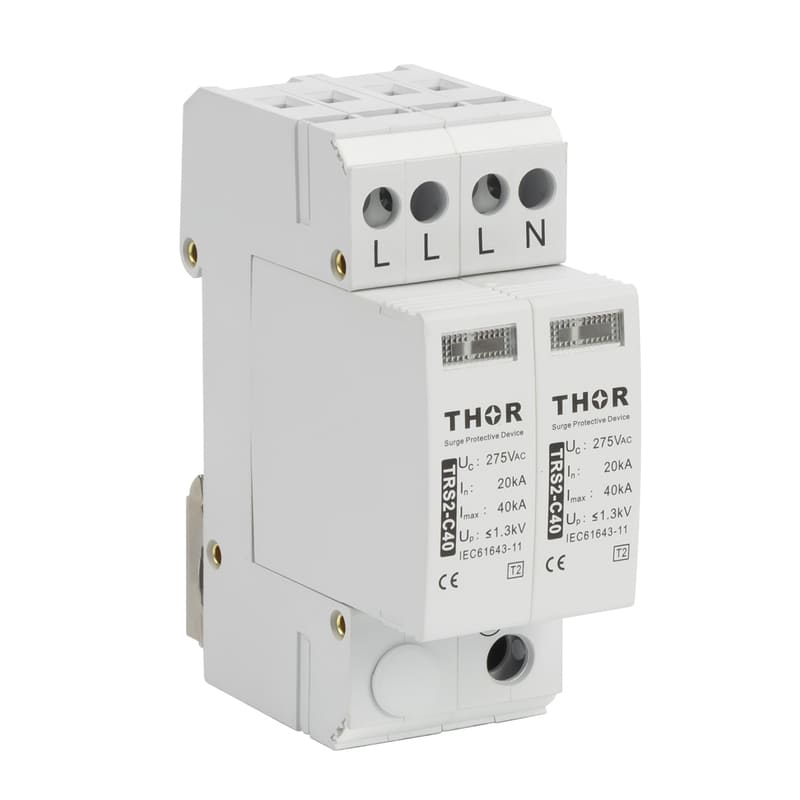
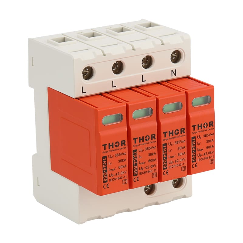
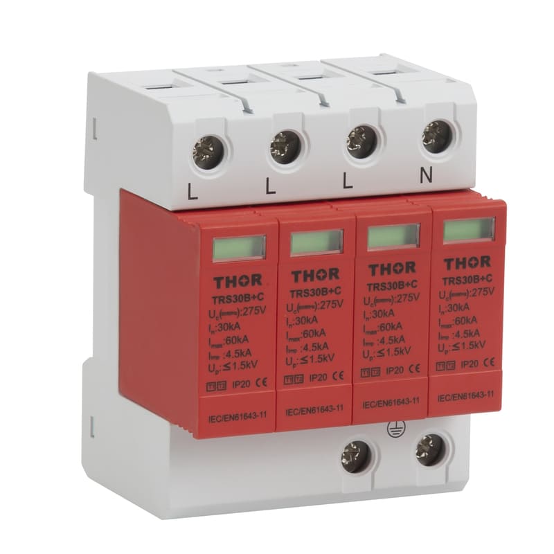
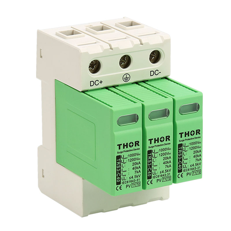
Thor Electric MOV-based pluggable SPDs
Thor Electric's TRS-B/C/D Type 2 families use MOV technology with pluggable modules, red visual fault indication, and optional remote signalling on selected configurations. Selection still depends on the system voltage, protection mode, installation arrangement, surge rating, and upstream coordination. Share those details through the Thor Electric contact page to discuss a suitable configuration and the supporting product documents.